Table of Contents
Advertisement
Quick Links
Advertisement
Table of Contents

Related Manuals for Weidmüller V-TEST II


Summary of Contents for Weidmüller V-TEST II
- Page 1 V-TEST II SPD component tester Manual...
-
Page 3: Table Of Contents
Table of contents Table of contents General ............... 4 Meaning of symbols ..........4 Safety ................5 SPD component tester ..........11 Intended use ............11 Unpacking the instrument ........12 Indicators, connections and controls ....13 User displays, menu structure and navigation..15 Splash screen ............ -
Page 4: General
General General Meaning of symbols Dangerous voltage! Danger to life or risk of serious injury. Disconnect system and instrument from power supply before beginning work. Caution! Please follow the documentation. This symbol warns of possible dangers that can arise during installation, commissioning and use. -
Page 5: Safety
Safety Safety Sicherheitshinweise Das Gerät darf nur von einer Elektrofachkraft in Betrieb genommen und gewartet werden, die mit den nationalen und internationalen Gesetzen, Vorschriften und Standards vertraut ist. GEFAHR Gefahr des elektrischen Schlags Die Kontakte des Prüfadapters führen während des Prüfvorgangs Hochspannung! ►... - Page 6 Safety Safety instructions The device must only be put into operation and maintained by qualified electricians who are famil- iar with national and international laws, provisions and standards. DANGER Risk of electric shock The contacts of the test adapter carry high voltage during the test procedure! ►...
- Page 7 Safety Consignes de sécurité Seuls des électriciens qualifiés et connaissant bien les lois, dispositions et normes nationales et internationales peuvent mettre en service et entretenir l’appareil. DANGER Risque de choc électrique Pendant la procédure de test, les contacts de l’adaptateur de test sont soumis à une tension élevée ! ►...
- Page 8 Safety Indicazioni di sicurezza Il dispositivo deve essere messo in funzione e sottoposto a manutenzione esclusivamente da elettricisti qualificati che conoscano le leggi, disposizioni e le norme nazionali e internazionali. PERICOLO Rischio di scossa elettrica Durante la procedura di test i contatti dell’adattatore di prova sono sottoposti a tensione elevata! ►...
- Page 9 Safety Indicaciones de seguridad Únicamente deben llevar a cabo la puesta en servicio y el mantenimiento del dispositivo electricis- tas cualificados familiarizados con las normas, leyes y disposiciones nacionales e internacionales. PELIGRO Riesgo de descarga eléctrica Tenga en cuenta que los contactos del adaptador de prueba pueden conducir alta tensión durante el procedimiento de prueba! ►...
- Page 10 Safety 安全规程 设备必须由具备资质的、熟悉国内国际法律、规定和标准的专业电气技术人员进行操作和维护。 危险 电击的危险 在测试过程中,测试用适配器的端头带有高电压! ► 请勿在爆炸性气体、蒸汽附近或潮湿环境中使用设备。 ► 只有在测试用适配器的所有 3 个插槽都被占用时才能按“TEST”键(1 个测试对象和 2 个空接 线盒)。 注意 带电部分危险 ► 请勿使用损坏的测试引线。 ► 首先请将测试引线连接至测试用适配器。然后将测试引线连接至设备。 ► 切勿将测试引线连接至带电的电缆。 ► 始终确保测试用适配器的所有 3 个插槽均被使用(1 个测试样本和 2 个空接线盒)。 ► 请勿将任何外来对象插入到测试用适配器的接触插座中。 注意 • 该设备仅可用于其既定用途。 • 如果设备损坏或发现了其他缺陷,则不得使用该设备。 • 设备不得打开、修改或改装。 •...
-
Page 11: Spd Component Tester
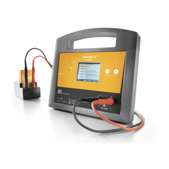
The surge protection component can be analyzed as part of an overvoltage protection device. The “V-TEST II” is suitable for Weidmüller surge protection devices of the “VPU AC” series. The built-in surge protection component is connected to the test instrument with the test leads and the test adapter. -
Page 12: Unpacking The Instrument
Unpacking the instrument Unpacking the instrument The standard product is supplied with the following items: • Instrument V-TEST II • Test adapter • Test leads • 3x dummy arresters • 5x AA NiMH batteries, 1.2 V, 2450 mAh • 12 V DC multi-system power adapter, 100...240 V AC, 2000 mA •... -
Page 13: Indicators, Connections And Controls
Scan for test data Weidmüller Interface GmbH & Co. KG IP20 Klingenbergstraße 26 High Voltage V-TEST II 2661040000 D-32758 Detmold Figure 1: Front view of instrument. Operating status LED (green) – pulses to indicate instrument is alive. Battery status LED (blue) – illuminates when battery is completely flat (< 1.12 V/cell) and requires recharging. - Page 14 Indicators, connections and controls Figure 2: Rear view of instrument. USB: for factory use and used during firmware update. DC power supply input: 12 V DC, 2000 mA. The unit is charged by external power supply (refer to Safety section). Only use the DC power supply provided.
-
Page 15: User Displays, Menu Structure And Navigation
User displays, menu structure and navigation User displays, menu structure and navigation Splash screen The Splash screen is used to greet the user and provide important safety information. The user is required to read the information and by clicking the Acknowledged... button is signifying that the potential hazard is understood and that precautions indicated will be followed (refer to Safety section). -
Page 16: Main Screen
User displays, menu structure and navigation Main screen The Main screen comprises four display panels. On the left is the buttons panel where the user selects various actions by clicking the required button. On the right is the output panel, where results of measurements are displayed. -
Page 17: About Screen
User displays, menu structure and navigation About screen The About screen provides information about the instrument manufacturing build. If the firmware is updated, this will be reflected in the firmware version shown. Change passcode screen The Change passcode screen allows the user to change the passcode required to unlock the instrument on startup. -
Page 18: Time/Date Screen
User displays, menu structure and navigation Time/Date screen The Time/Date screen allows the user to set the time and date. Start by clicking the DD/MM/YY button. This will toggle between DD/MM/YY and HH:MM:SS setting. The up/down arrows are used to adjust each digit of the time or date. -
Page 19: Measurement Screen
User displays, menu structure and navigation Measurement screen The Measurement screen is where the user selects the rate of voltage ramp (ramp rate) used in the testing of gas discharge tubes, and the constant current used in the testing of metal oxide varistors and avalanche breakdown diodes. -
Page 20: Battery Screen
User displays, menu structure and navigation Battery screen The Battery screen provides information of the status of the instrument battery (refer to Battery monitoring section). The battery icon shows either the % remaining, or the of AC ~ symbol if the DC charger is connected. -
Page 21: Gdt Screen
User displays, menu structure and navigation GDT screen The GDT screen is where the firing voltage of the GDT under test is displayed. The measurement is performed by pressing the TEST button on the front of the instrument. The rate of voltage ramp in V/s used in this measurement is configured in the Measurement screen. -
Page 22: Using Instrument
Using instrument Using instrument Power on With instrument in its off state, momentarily depress the ON/OFF button on the front panel to turn the instrument on. Enter the passcode (if Require passcode option is enabled in the Set Options menu) and click the Acknowledge... -
Page 23: User Commissioning
User commissioning User commissioning Step 1 Touch panel calibration: The user is requested to ‘touch’ using the stylus on the top right-hand corner of the frame, and then again on the bottom left-hand corner. If the touch is within expected limits, the coordinates are accepted and the display calibrated accordingly. -
Page 24: System Status
User commissioning System status From the Main screen navigate to: SETUP / System Status The System Status menu, allows the user to select one of the following sub-menus: • Battery • Update Click the < BACK button to return to the Main screen. About instrument From the Main screen navigate to: SETUP / About Displays information about the instrument including:... -
Page 25: Measuring
Measuring Measuring Auto / Manual measurement mode Measurements of surge protective components (SPCs) or surge protective devices (SPDs) can be performed in one of two ways with this instrument – using the auto mode or using the manual mode. The auto mode is selected by clicking the AUTO button on the button panel. -
Page 26: Measuring Movs
Measuring Measuring MOVs To measure an MOV component (Varistor), or an SPD comprising several metal oxide varistor internally: Step 1 Decide if using the auto or manual detection mode by pressing either the AUTO button or the MOV button respectively. Step 2 Set the required constant current for the measurement (refer to Measurement screen section). -
Page 27: Measuring Tvss
Measuring Measuring TVSs Transient Voltage Suppressors (TVS), also called Avalanche Breakdown Decides (ABDs), are tested in much the same way as an MOV. In the TVS mode the maximum voltage used to drive the constant current is limited to 200 V since most TVS devices are below this voltage. To perform a measurement, please refer to the steps in the Measuring MOVs section. -
Page 28: Measuring Spds
Measuring Measuring SPDs Surge Protective Device (SPDs) in their simplest form comprise one or more non-linear surge protective components (SPC), a disconnector (thermal or overcurrent) and some form of status indicator (mechanical or electronic). The internal surge protective components are generally of two types – voltage switching (GDT, Thyristor etc.) and voltage limiting (MOV, ABD, TVS etc.). -
Page 29: Updating The Firmware
Measuring Updating the firmware The firmware developed for the instrument has been extensively tested and found to be stable and reliable in use, however as with all software, unanticipated behavior may occur requiring correction, or improvements with additional features and functionality may be released from time-to-time. The firmware in the instrument incorporates its own ‘bootloader’... - Page 30 Measuring To upgrade the firmware please follows these steps: Turn on the instrument. From the Main screen click to reach the SETUP / System Status sub-menu. Click Update in the buttons panel. Follow user prompts – an < Exit button is provided at the last prompt should the user wish to exit back to the MAIN MENU at this stage.
-
Page 31: Maintenance
Maintenance Maintenance Cleaning Periodically wipe the case and display with a damp cloth and mild detergent. Do not use abrasives or solvents. Dirt or moisture in the terminals can affect readings and should be removed when evident. To clean the terminals: Ensure that the instrument is in the shutdown state. -
Page 32: Replacing Clock Battery
Maintenance Replacing clock battery The real-time-clock (RTC) which maintains the time and date on the main screen footer is backed up with an internal 3 V Lithium coin cell battery (CR2032). In order to replace this battery, the back cover of the instrument must be removed. -
Page 33: Specifications
Specifications Specifications Features • Self-calibration • Illuminated color TFT display and touch screen interface • User configurable menu and options • Auto-detection of type of SPD component connected • Measurement programs for MOVs, GDTs and ABDs • Test GDTs and MOVs up to 1500 V DC •... -
Page 34: Physical Dimensions
Physical dimensions Physical dimensions 204,5 mm 222 mm 81 mm 2661740000/03/02-2021... -
Page 35: Surge Protection Products From Weidmüller
Surge protection products from Weidmüller Surge protection products from Weidmüller Test results MOV @ 1 mA GDT @ 100 V/s Order Product designation number Minimum Maximum Minimum Maximum value value value value in V in V in V in V VPU AC I 275V 25kA LCF S VPU AC I 1 275/25 LCF S 2726620000... - Page 36 Surge protection products from Weidmüller Test results MOV @ 1 mA GDT @ 100 V/s Order Product designation number Minimum Maximum Minimum Maximum value value value value in V in V in V in V VPU AC I 300V 12.5kA VPU AC I 0 300/12.5 2591370000 VPU AC I 1 300/12.5...
- Page 37 Surge protection products from Weidmüller Test results MOV @ 1 mA GDT @ 100 V/s Order Product designation number Minimum Maximum Minimum Maximum value value value value in V in V in V in V VPU N-PE VPU AC I 1 N-PE 305/50 2591570000 n.a.
- Page 38 Surge protection products from Weidmüller Test results MOV @ 1 mA GDT @ 100 V/s Order Product designation number Minimum Maximum Minimum Maximum value value value value in V in V in V in V VPU AC II 300V 50kA Y VPU AC II 1 R 300/50 Y 2639350000 VPU AC II 1+1 R 300/50 Y...
- Page 39 Surge protection products from Weidmüller Test results MOV @ 1 mA GDT @ 100 V/s Order Product designation number Minimum Maximum Minimum Maximum value value value value in V in V in V in V VPU AC II 750V 35kA VPU AC II 0 750/35 2591290000 1215...
- Page 40 Surge protection products from Weidmüller Test results MOV @ 1 mA GDT @ 100 V/s Order Product designation number Minimum Maximum Minimum Maximum value value value value in V in V in V in V VPU AC II US 4 240/50 2736400000 VPU AC II US 4 R 240/50 2736410000...
- Page 41 Surge protection products from Weidmüller Test results MOV @ 1 mA GDT @ 100 V/s Order Product designation number Minimum Maximum Minimum Maximum value value value value in V in V in V in V VPU AC II US 400V 50kA VPU AC II US 0 400/50 2730690000 VPU AC II US 1 400/50...
- Page 44 www.weidmueller.com Weidmüller Interface GmbH & Co. KG Klingenbergstraße 26 32758 Detmold Germany T +49 5231 14-0 F +49 5231 14-292083 Order number: www.weidmueller.com 2661740000/03/02-2021...
Need help?
Do you have a question about the V-TEST II and is the answer not in the manual?
Questions and answers