Table of Contents
Advertisement
Quick Links
TWG Headquarters, 11135 S
James Ave Jenks, OK 74037 USA
(918) 298-8300
salesinfo@dovertwg.com
PMC 256
THE LOGICAL CHOICE
INSTRUCTION AND PARTS MANUAL
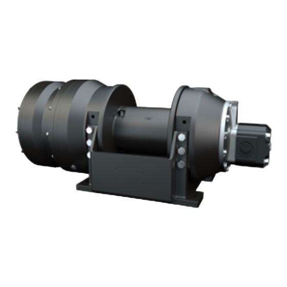
MODEL M12
FREESPOOL
PLANETARY HYDRAULIC WINCH
READ THIS MANUAL BEFORE INSTALLING, OPERATING OR
SERVICING THIS PRODUCT. THIS MANUAL CONTAINS IMPORTANT
INFORMATION. MAKE THIS MANUAL AVAILABLE TO ALL PERSONS
RESPONSIBLE FOR THE OPERATION, INSTALLATION, SERVICING
AND MAINTENANCE OF THIS PRODUCT.
TWG Canada, 19350 22nd Ave
Surrey, BC V3Z 3S6 CANADA
(604) 547-2100
salesinfo@dovertwg.com
07 2020
Advertisement
Table of Contents

Subscribe to Our Youtube Channel
Related Manuals for Dover TWG PULLMASTER M12


Summary of Contents for Dover TWG PULLMASTER M12
- Page 1 THE LOGICAL CHOICE INSTRUCTION AND PARTS MANUAL MODEL M12 FREESPOOL PLANETARY HYDRAULIC WINCH TWG Headquarters, 11135 S TWG Canada, 19350 22nd Ave James Ave Jenks, OK 74037 USA Surrey, BC V3Z 3S6 CANADA (918) 298-8300 (604) 547-2100 salesinfo@dovertwg.com salesinfo@dovertwg.com READ THIS MANUAL BEFORE INSTALLING, OPERATING OR SERVICING THIS PRODUCT.
- Page 2 Effective 2011/10/01 UPERSEDES RIOR ARRANTIES LIMITED WARR ANTY 50130-0 Seller warrants that each article (whether Gear Drive Products, Brake Products and/or Winch Products, all of which are covered hereunder) sold under this order shall at the time of shipment (i) conform to applicable specifications, and (ii) be free from defects in material and workmanship during normal and ordinary use and service (the "Warranty").
-
Page 3: Safety Recommendations
SAFETY RECOMMENDATIONS Definition: Caution indicates a potentially hazardous situation which, if not avoided may DANGER result in minor or moderate injury Definition: Warning indicates a potentially FAILURE TO COMPLY WITH THE FOLLOWING SAFETY hazardous situation which, if not avoided could result in death or serious injury. - Page 4 DESCRIPTION OF THE MODEL M12F GENERAL DESCRIPTION: The PULLMASTER Model M12 with freespool is a planetary, hydraulic winch having equal speed in both directions. The main components of this unit are: ✛ hydraulic gear motor ✛ multi-disc brake with static and dynamic function ✛...
-
Page 5: Explanation Of Model Coding
EXPLANATION OF MODEL CODING X - XX - XX - XX X - X XXXX BASIC UNIT SERIES M = Equal speed in both directions SIZE OF UNIT REDUCTION RATIO Only used for non standard reduction ratios TYPE OF BRAKE Automatic brake, clockwise drum rotation, internal circulation flow Automatic brake, external brake release, clockwise drum rotation, internal circulation flow... - Page 6 OPTIONS COUNTERCLOCKWISE ROTATION: The drum rotation of the standard PULLMASTER Model M12 planetary winch is clockwise for hoisting when looking at the hydraulic motor of the winch. Drum rotation for counterclockwise hoisting direction is available as an option. EXTERNAL BRAKE RELEASE: PULLMASTER planetary winches can be supplied with an external brake release which permits release of the automatic disc brake from an external pressure source.
-
Page 7: Specifications
SPECIFICATIONS Performance specifications are based on standard hydraulic motor, gear ratio and cable drum with 5/8 inch diameter wire rope. For other cable drums refer to APPENDIX A. For other reductions or motors, refer to supplement inside back cover. Performance specifications for winches supplied with optional motors are provided in attached supplement. -
Page 8: Performance Graphs
PERFORMANCE GRAPHS PG-M12-B LINE PULL VS. OIL PRESSURE LINE PULL - kN 17.8 26.7 35.6 44.5 53.4 2200 2000 1600 1200 2000 4000 6000 8000 10000 12000 LINE PULL - lb LINE SPEED VS. OIL VOLUME LINE SPEED - m/min LINE SPEED - fpm Performance graphs are based on standard hydraulic motor, gear ratio and cable drum with 5/8 inch diameter wire rope. -
Page 9: Typical Hydraulic Circuit
TYPICAL HYDRAULIC CIRCUIT HC-M12-F 400 PSI [28 BAR] PRESSURE REQUIRED FOR MODELS SUPPLIED 800 PSI [55 BAR] WITH FREESPOOL 2(US)GPM [8 L/MIN] OPTION REQUIRED FOR MODELS SUPPLIED WITH EXTERNAL BRAKE RELEASE OPTION CIRCULATION SUPPLY LINE M12: 3.5 (US) GPM [13 LPM] H12: 4.5 (US) GPM [17 LPM] (EXTERNAL CIRCULATION MODELS ONLY) - Page 10 RECOMMENDATIONS HYDRAULIC FLUID: HYDRAULIC PRESSURE RELIEF: The hydraulic circuit for the PULLMASTER planetary The hydraulic fluid selected for use with PULLMASTER winch requires a pressure relief set at the operating planetary winches should be a high grade, petroleum pressure (see SPECIFICATIONS). Usually, a pressure based fluid, with rust, oxidation and wear resistance.
-
Page 11: Installation Instructions
INSTALLATION INSTRUCTIONS DANGER FAILURE TO FOLLOW INSTALLATION INSTRUCTIONS WILL RESULT IN PROPERTY DAMAGE, SEVERE INJURY OR DEATH. The initial installation or mounting of a PULLMASTER planetary winch is critically important for proper operation and performance. If the winch is mounted to an uneven surface, the centre line of the unit can be distorted to a point where the winch will not operate in either direction. - Page 12 OPERATING INSTRUCTIONS DANGER FAILURE TO FOLLOW OPERATING INSTRUCTIONS WILL RESULT IN PROPERTY DAMAGE, SEVERE INJURY OR DEATH. After the PULLMASTER planetary winch has been installed in accordance with the INSTALLATION INSTRUCTIONS, the wire rope can be fastened to the cable drum. IMPORTANT: The ropes, chains, slings, etc.
-
Page 13: Troubleshooting
TROUBLE SHOOTING GENERAL: In most cases, when the hydraulic winch does not perform satisfactorily, the cause of malfunction is found somewhere in the hydraulic circuit. Before the winch is removed from its mounting and disassembled, all of the hydraulic circuit components should be checked for proper function. IMPORTANT: The hydraulic oil volume relates to the line speed or rpm of the winch. - Page 14 TROUBLE SHOOTING CONTINUED PROBABLE CAUSE FAILURE Brake will not hold. Brake plates or divider plates have been damaged by contamination in the hydraulic fluid, or lack of circulation flow in the brake housing. Brake piston is seized in the brake housing because of contamination in the hydraulic fluid.
- Page 15 SERVICE INSTRUCTIONS GENERAL: Before attempting disassembly of the PULLMASTER Model M12 planetary winch with freespooling, the following instructions for disassembly and reassembly should be read and understood: It is suggested that all expendable parts, such as O-rings and oil seals, are not reused on reassembly. It is therefore important to have a seal kit (Part No.
- Page 16 SERVICE INSTRUCTIONS CONTINUED with the exception of the motor adaptor item 800, are standard parts of the hydraulic motor, having a 2 inch gear section. All of these parts can be ordered from PULLMASTER or Authorized Distributors/Dealers in Canada, the United States and in most overseas areas.
- Page 17 SERVICE INSTRUCTIONS CONTINUED 7) Remove six friction plates item 715, together with seven divider plates item 714, and inspect for damage or wear. Plates should be flat and smooth. Plates should not show heat discoloration. Paper material on friction plates should be intact and grooved.
- Page 18 SERVICE INSTRUCTIONS CONTINUED 8) Withdraw freespool extender item 262, and freespool coupling item 260, from inside of cable drum item 500. 9) Remove and inspect two thrust washers item 285, and thrust bearing item 287. Replace if cracked or otherwise damaged. 10) To separate cable drum from final housing, first remove circlip item 513.
- Page 19 SERVICE INSTRUCTIONS CONTINUED 4) Reassemble primary planet hub assembly. Press sungear stopper item 444, into primary planet hub item 400. Press needle bearing item 423, into primary planet gear item 420. Position thrust washers item 421, on either side of planet gear and press planet pin item 410, into primary planet hub item 400. Retain with circlip item 411. 5) Install primary planet hub onto end of final sungear item 340, inside of cable drum item 500.
- Page 20 SERVICE INSTRUCTIONS CONTINUED Install new, well-greased O-ring item 707, onto motor adaptor pilot. 12) Position motor adaptor, with brake release pressure transfer holes of motor adaptor and brake housing aligned. Tighten 12 capscrews item 821, and lockwashers item 823, one turn at a time to evenly compress springs. 13) Attach base item 550, to winch using 12 capscrews item 551, and 12 lockwashers item 553.
-
Page 21: Recommended Maintenance
RECOMMENDED MAINTENANCE Winch gear train lubricating oil should be changed after the initial six months or 50 hours of operation, whichever comes first. Lubricating oil should then be changed every 12 months or 500 operating hours, whichever comes first. Hydraulic system fluid should be changed at least once every 12 months. For optimum performance over an extended period of time, the following preventive maintenance service should be done every 12 months or 500 operating hours (whichever comes first): 1) Disconnect all hydraulic hoses and remove the winch from its mounting. - Page 22 PARTS REFERENCE - FINAL DRIVE DESCRIPTION ITEM NO. QTY. PART NO. 20283 FINAL HOUSING 25095 BALL BEARING # 6020 25142 OIL SEAL 25093 CIRCLIP ROTOR CLIP HO-600 21814 END COVER 25032 PIPE PLUG 1/2 - 14 NPT 25088 O-RING -279 13" ID 1/8" CS 20161 RETAINING RING INT.
-
Page 23: Final Drive Group
FINAL DRIVE GROUP G1035 Groups drawings may reference more parts than are actually present in a specific assembly. Parts that are referenced on the drawing but are not on the PARTS REFERENCE list should be ignored. 256 REV.950401 PAGE 21... -
Page 24: Parts Reference - Brake Group
PARTS REFERENCE - BRAKE GROUP DESCRIPTION ITEM NO. QTY. PART NO. 25095 BALL BEARING #6020 20095 PLANET HUB 21169 PLANET PIN 25060 CIRCLIP ROTOR CLIP C-62 21176 INTERNAL GEAR STOPPER 25119 CIRCLIP ROTOR CLIP SH-62 20101 PLANET GEAR 25064 THRUST WASHER TORRINGTON # TRA 1018 25269 NEEDLE BEARING TORRINGTON # BH1016 21174... -
Page 25: Brake Group
BRAKE GROUP G1034-A Group drawings may reference more parts than are actually present in a specific assembly. Parts that are referenced on the drawing but are not on the PARTS REFERENCE list should be ignored. PAGE 23 256 REV.970801... -
Page 26: Parts Reference - Motor Group
PARTS REFERENCE - MOTOR GROUP DESCRIPTION ITEM NO. QTY. PART NO. 21390 MOTOR ADAPTOR 25310 O-RING - 012 3/8" ID 1/16" CS 25370 PIPE PLUG 1/16 - 27 NPT 25040 PIPE PLUG 1/8 - 27 NPT 25118 CAPSCREW - HEX HEAD 3/8 - 16 NC X 1.25 GRADE 5 25037 LOCKWASHER 3/8"... -
Page 27: Motor Group
MOTOR GROUP G1033-A Group drawings may reference more parts than are actually present in a specific assembly. Parts that are referenced on the drawing but are not on the PARTS REFERENCE list should be ignored. 256 REV.970801 PAGE 25... -
Page 28: Installation Drawing
INSTALLATION DRAWING I1017-1-E 256 REV.051117 PAGE 26... -
Page 29: Installation Dimensions
INSTALLATION DIMENSIONS Dimensions in inches (Dimensions in millimeters) DRUM 14.6 10.0 15.9 15.6 19.1 17.000 23.8 10.6 8.56 11.000 17.5 (194) (371) 254) (173) (404) (396) (486) (431.80) (604) (269) (217) (279.40) (445) 14.6 10.0 15.9 15.6 19.1 17.000 23.8 10.6 8.56 11.000... -
Page 30: Assembly Drawing
ASSEMBLY DRAWING G1033-A & G1034-A & G1035 256 REV.970801 PAGE 28... - Page 31 APPENDIX A LINE PULL LINE SPEED AT MAXIMUM AT MAXIMUM LUBRICATING WIRE ROPE STORAGE CABLE DRUM SIZES VOLUME* PRESSURE* VOLUME FEET INCHES DRUM REQUIRED (MILLIMETERS) (METERS) CODE U.S. POUNDS FEET/MINUTE GALLONS (KILONEWTONS) (METERS/MINUTE) (LITERS) BARE FULL BARE FULL BARREL FLANGE LENGTH 5/8 in 9/16 in 1/2 in...
- Page 32 APPENDIX B ITEM NO. DESCRIPTION FREESPOOL CABLE DRUM BASE CIRCLIP EXTENDER DRUM CODE Part No. Part No. Part No. Quantity 21670 21528 20148 21670 21529 20148 21680 21535 20293 21670 21537 20148 21670 21538 20148 21680 21539 20293 - 11 21680 21679 21132...
- Page 33 APPENDIX C BRAKE CODE - 10 ITEM PART DESCRIPTION PART NUMBERS SHUTTLE 20849 20849 20849 20849 ORIFICE 21483 21483 21483 21483 PLUG 1/8-27 NPT 25040 25040 25040 25040 PIPE PLUG 1/8-27 NPT 25040 25040 25040 25040 PIPE PLUG 1/8-27 NPT 25622 25622 25622...
-
Page 34: Bolt Torque Chart
BOLT TORQUE CHART BOLT DIAMETER TORQUE TORQUE Inches Lb-ft 5/16 7/16 9/16 1085 1000 1356 1200 1627 1500 2034 NOTE: Unless otherwise specified, torque bolts per above chart. 256 REV.950401 PAGE 32...
Need help?
Do you have a question about the TWG PULLMASTER M12 and is the answer not in the manual?
Questions and answers