
Summary of Contents for d2itsu CDV-46
- Page 1 SERIE INSTALLATION AND CDV-46 MAINTENANCE EDITION MANUAL USER MANUAL WIRED CONTROLLER Model: CDV-46...
- Page 3 To Users Thank you for selecting Daitsu’s product. Please read this instruction manual carefully before installing and using the product, so as to master and correctly use the product. In order to guide you to correctly install and use our product and achieve expected operating effect, we hereby instruct as below: (1) This appliance is not intended for use by persons (including children) with reduced physical, sensory or mental capabilities,...
- Page 4 unnecessary maintenance, violation of related national laws and rules and industrial standard, and violation of this instruction manual, etc., we will bear no liability. (5) The final right to interpret for this instruction manual belongs to Daitsu. This marking indicates that this product should not be disposed with other household wastes throughout the EU.
-
Page 5: Table Of Contents
Contents 1 SAFETY NOTICES (PLEASE BE SURE TO ABIDE ) ....1 2 OPERATION NOTICES ............2 3 DISPLAY ................3 3.1 LCD OF WIRED CONTROLLER ..........3 3.2 LCD DISPLAY INSTRUCTION ............ 4 4 BUTTONS ................7 4.1 BUTTON GRAPHICS ..............7 4.2 FUNCTION INSTRUCTION OF BUTTONS ........ - Page 6 6.12 FILTER CLEAN REMINDER SETTING ........54 6.13 X-FAN SETTING ..............58 6.14 ABSENCE SETTING ............... 59 6.15 REMOTE SHIELD FUNCTION ..........59 6.16 CHILD LOCK FUNCTION ............60 6.17 GATE-CONTROL FUNCTION ..........60 7 ERROR DISPLAY ..............60 7.1 TABLE OF ERROR CODES FOR OUTDOOR UNIT ....62 7.2 TABLE OF ERROR CODES FOR INDOOR UNIT ....
-
Page 7: Safety Notices (Please Be Sure To Abide )
Wired Controller CDV-46 1 SAFETY NOTICES (PLEASE BE SURE TO ABIDE ) Warning: If not abide strictly, it may cause severe damage to the unit or the people. Note: If not abide strictly, it may cause slight or medium damage to the unit or the people. -
Page 8: Operation Notices
Wired Controller CDV-46 2 OPERATION NOTICES The power supply for all indoor units must be unified. Prohibit installing the wired controller at wet or sunshine places. Do not knock, throw or frequently disassemble the wired controller. Do not operate the wired controller with wet hands. -
Page 9: Display
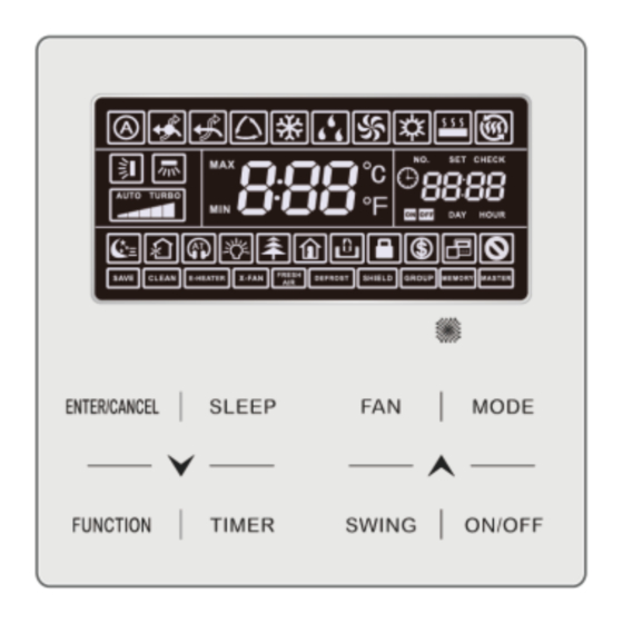
Wired Controller CDV-46 3 DISPLAY Fig. 3.1 Appearance of wired controller 3.1 LCD OF WIRED CONTROLLER Fig. 3.2 LCD graphics of wired controller... -
Page 10: Lcd Display Instruction
Wired Controller CDV-46 3.2 LCD DISPLAY INSTRUCTION Table 3.1 LCD display instruction Symbols Instructions Up and down swing function Left and right swing function It's valid under Save mode and displays during setting process. Temperature lower limit for Cooling: Limit the minimum temperature value under Cooling or Dry mode. - Page 11 Wired Controller CDV-46 Symbols Instructions When inquiring or setting project number of indoor unit, it displays "NO." icon Floor Heating mode (When Heating and Floor Heating simultaneously shows up, it indicates 3D Heating is activated.) Display "SET" icon under parameter setting interface Space Heating mode Display "CHECK"...
- Page 12 Wired Controller CDV-46 Symbols Instructions Reserved function Absence function Outdoor unit defrosting status Gate-control function Shielding status Child Lock status One wired controller controls multiple indoor units Save status of indoor unit It indicates the current wired controller is the slave wired...
-
Page 13: Buttons
Wired Controller CDV-46 4 BUTTONS 4.1 BUTTON GRAPHICS Fig. 4.1 Button graphics 4.2 FUNCTION INSTRUCTION OF BUTTONS Table 4.1 Function instruction of buttons Buttons Instructions ENTER/CANCEL Select and cancel function (1) Set operating temperature of indoor unit (2) Set Timer... -
Page 14: Installation And Commissioning
Wired Controller CDV-46 Buttons Instructions SLEEP Set Sleep mode Switch among auto, low speed, low-medium speed, medium speed, medium-high speed, high speed and turbo status Switch Auto,Cooling, Dry, Fan, Heating, Floor Heating, 3D Heating and Space Heating modes for indoor unit. - Page 15 Wired Controller CDV-46 Fig. 5.1.1 Parts of wired controller Panel of wired Self-tapping Screw ST3.9X25 Soleplate of wired Name controller controller Q'ty...
-
Page 16: Installation Of Wired Controller
Wired Controller CDV-46 Edition Two : Fig. 5.1.2 Parts of wired controller Panel of wired Self-tapping Screw Soleplate of wired Name Screw M4×25 controller ST3.9X25 MA controller Q'ty... - Page 17 Wired Controller CDV-46 5.1 INSTALLATION OF WIRED CONTROLLER 5.1.1 Communication Line Selection Fig. 5.2 Length of communication line Total length of Wire size communication line Wire material Material between indoor unit (mm /AW Remarks type standard and wired controller L (m/feet)
- Page 18 Wired Controller CDV-46 Materials of communication line for wired controller must be selected according to this instruction manual strictly 5.1.2 Installation requirements (1) Prohibit installing the wired controller at wet places. (2) Prohibit installing the wired controller at direct sunshine places.
- Page 19 Wired Controller CDV-46 5.1.3 Wiring Requirements There are four network wiring methods between wired controller and indoor unit: Fig. 5.3 One wired controller controls Fig. 5.4 Two wired controllers control one indoor unit one indoor unit...
- Page 20 Wired Controller CDV-46 Fig. 5.5 One wired controller controls multiple indoor units simultaneously...
- Page 21 Wired Controller CDV-46 Fig. 5.6 Two wired controllers control multiple indoor units simultaneously Wiring instructions: (1) When one wired controller controls multiple indoor units simultaneously, the wired controller can connect to any one indoor unit, but the connected indoor unit must be the same series indoor unit. The total quantity of indoor unit controlled by wired controller can't exceed 16 sets, and the connected indoor unit must be within the same indoor unit's network.
- Page 22 Wired Controller CDV-46 (3) When two wired controllers control multiple indoor units, wired controller can connected to any one indoor unit, while the connected indoor unit should be the same series indoor unit. The addresses of those two wired controllers should be different.
- Page 23 Wired Controller CDV-46 5.1.4 Installation There’re two editions of wired controller. The Installation way is different. Installation way one : Fig. 5.7 Installation diagram for wired controller...
- Page 24 Wired Controller CDV-46 Fig. 5.7 is the simple installation process of wired controller; please pay attention to the following items: (1) Before installation, please cut off the power for indoor unit. (2) Pull out the two-core twisted pair from the installation hole on wall, and then pull this wire through the "...
- Page 25 Wired Controller CDV-46 Fig. 5.8 Installation diagram for wired controller Fig. 5.8 is the simple installation process of wired controller; please pay attention to the following items: (1) Before installation, please cut off the power for indoor unit. (2) Pull out the two-core twisted pair from the installation hole on wall, and then pull this wire through the "...
- Page 26 Wired Controller CDV-46 (3)Stick the bottom plate of wired controller on the wall and then use Self-tapping Screw ST3.9X25 MA or Screw M4×25 to fix Soleplate and installation hole on wall together. (4) Connect two-core twisted pair to H1 and H2 wiring column and then fix the screws.
-
Page 27: Commissioning
Wired Controller CDV-46 5.2 COMMISSIONING 5.2.1 Set Master Indoor Unit Under Off status, long press MODE button for 5s to set the corresponding indoor unit of wired controller as master indoor unit. “MASTER” icon will be light after finishing setting. - Page 28 Wired Controller CDV-46 Table 5.1 Parameters viewing list Parameter Parameter Parameter Viewing method code name range In “C00” status, Timer zone shows the current indoor Entrance of unit project number. When one wired controller is adjustable controlling multiple indoor units, then only the parameter smallest project number will be displayed.
- Page 29 Wired Controller CDV-46 Parameter Parameter Parameter Viewing method code name range Operation method: Enter viewing: press MODE button in “C06” status to enter the interface of viewing priority operation. Press “ ” or “ ” button to select indoor unit.
- Page 30 Wired Controller CDV-46 Parameter Parameter Parameter Viewing method code name range View the indoor unit quantity in the case that one wired Timer zone: displays the indoor unit quantity controller 1-16 controlled by the wired controller controls several indoor units...
- Page 31 Wired Controller CDV-46 Parameter Parameter Parameter Viewing method code name range Operation method: Enter viewing, short-press “MODE” button in “C18” status to turn on the function of one-button viewing indoor unit project code, and the wired controller will enter the interface of viewing indoor unit project code.
- Page 32 Wired Controller CDV-46 Parameter Parameter Parameter Viewing method code name range Operation method: Enter viewing, short-press “MODE” button in “C20” status to enter the interface of viewing air outlet View the air temperature of Fresh Air Indoor Unit. Press “...
- Page 33 Wired Controller CDV-46 finish setting. (3) Press ENTER/CANCEL button to return to last step until exists setting parameters. The parameter setting list is as following: Table 5.2 Parameter setting list Parameter Parameter Default Parameter name Note code range value 00: do not change...
- Page 34 Wired Controller CDV-46 Parameter Parameter Default Parameter name Note code range value 00: forbid this Set quantity of Set the corresponding value function group control according to the connected 01-16: indoor unit indoor units indoor unit quantity. quantity Set unit of...
- Page 35 Wired Controller CDV-46 Parameter Parameter Default Parameter name Note code range value Clock Timer 00: once Available only when timer is repetition is valid 01: repeat everyday set to clock timer. Cooling setting 17°C~30°C(63°F~86° 25°C When the temperature unit temperature (77°F)
- Page 36 Wired Controller CDV-46 Parameter Parameter Default Parameter name Note code range value Air outlet temperature setting 16°C~30°C(61° F ~ 18°C Only applicable to Fresh Air for Fresh Air Indoor 86° F ) (64°F) Indoor Unit Unit in cooling* Air outlet temperature setting 16°C~30°C(61°...
-
Page 37: Operation Instructions
Wired Controller CDV-46 6 OPERATION INSTRUCTIONS 6.1 ON/OFF Press ON/OFF button to turn on the unit. Press ON/OFF button again to turn off the unit. The interfaces of On/Off status are shown in fig. 6.1 ~ 6.4. Fig. 6.1 Interface of On status in Celsius Fig. 6.2 Interface of Off status in Celsius... -
Page 38: Mode Setting
Wired Controller CDV-46 Fig. 6.3 Interface of On status Fig. 6.4 Interface of Off status in Fahrenheit in Fahrenheit 6.2 MODE SETTING Under On status, pressing MODE button can set mode circularly as:... -
Page 39: Temperature Setting
Wired Controller CDV-46 Note: the available modes are different for different models, the wired controller will automatically select mode setting range according to the model of indoor unit. The Auto mode can be only set at the master indoor unit. -
Page 40: Fan Setting
Wired Controller CDV-46 can not be adjusted by pressing “ ” or “ ”. When the wired controller is connected with a Fresh Air Indoor Unit, fresh air indoor unit code “FAP” will be displayed as shown below. Setting temperature won’t be displayed and can’t be adjusted via “... -
Page 41: Timer Setting
Wired Controller CDV-46 (2) Turbo function setting Start turbo function: In unit on status, press “FUNCTION” button to switch to Turbo function with Turbo function icon “ ”blinking, and then press “ENTER/CANCLE” button to start Turbo function. When Turbo function is activated, Turbo function icon “... - Page 42 Wired Controller CDV-46 6.5.1 General Timer Unit On/Off after a desired hour can be set through general timer. Set Timer: when timer is not set, press TIMER button to enter timer setting and “HOUR” icon is blinking. Press “ ” or “...
- Page 43 Wired Controller CDV-46 Fig. 6.5 Timer Off setting in unit On status in Celsius...
- Page 44 Wired Controller CDV-46 Fig. 6.6 Timer Off setting in unit On status in Fahrenheit 6.5.2 Clock Setting Clock display: when the timer setting way is clock timer, timer zone displays system clock in unit On and Off status. icon is bright and the clock can be set at this time.
- Page 45 Wired Controller CDV-46 6.5.3 Clock Timer Unit On/Off at a certain time can be set through clock timer. Set Timer: (1) Press TIMER button to enter timer on setting and the “ON” icon is blinking; (2) Press “ ” or “...
- Page 46 Wired Controller CDV-46...
- Page 47 Wired Controller CDV-46 Fig. 6.7 Unit On/Off time setting in unit On status in Celsius...
- Page 48 Wired Controller CDV-46 Fig. 6.8 Unit On/Off time setting in unit On status in Fahrenheit...
-
Page 49: Swing Setting
Wired Controller CDV-46 6.6 SWING SETTING In unit on status, up & down swing function and left & right swing function can be set. (1) Up & down swing function Up & down swing function has two modes: simple swing mode and fixed-angle swing mode. -
Page 50: Quiet Setting
Wired Controller CDV-46 6.7 QUIET SETTING Quiet Function: decrease the noise of indoor unit and achieve the quiet effect. Quiet function has two modes: Quiet mode and Auto Quiet mode. It is available only in Auto, Cooling, Dry, Fan, Heating, 3D heating, Space heating mode. - Page 51 Wired Controller CDV-46 Fig. 6.9 Setting of Quiet function in Celsius...
- Page 52 Wired Controller CDV-46 Fig. 6.10 Setting of Quiet function in Fahrenheit Note: When Quiet function is enabled, indoor unit will operate at quiet fan speed. Fan speed is lowered so as to reduce the noise of indoor fan motor. When Auto Quiet function is enabled, indoor unit will change fan speed automatically according to room temperature.
-
Page 53: Sleep Setting
Wired Controller CDV-46 6.8 SLEEP SETTING Sleep Function: in this mode, the unit will operate according to the preset sleep curve to provide comfortable sleep environment. Turn on/off Sleep Function: in unit On status, press SLEEP button to activate. or cancel Sleep function. - Page 54 Wired Controller CDV-46 Fig.6.11 Turn on Air Function in Celsius...
- Page 55 Wired Controller CDV-46 Fig.6.12 Turn on Air Function in Fahrenheit...
-
Page 56: Light On/Off Setting
Wired Controller CDV-46 Note: Air function is only effective for units with air function and fresh air motorized air valve (abbr. fresh air valve). The following table indicates the opening time of fresh air valve per unit of time (60min) corresponding to the level of Air setting. Opening time of fresh air valve is the initial N minutes per unit of time. -
Page 57: Save Setting
Wired Controller CDV-46 When there is no button operation on the wired controller or no remote control signal is received for 20s continuously: If Light function is activated, the back light of LCD will turn to half bright. If Light function is off, the back light of LCD will be off. - Page 58 Wired Controller CDV-46 Fig.6.13 Save Setting for Cooling in Celsius...
- Page 59 Wired Controller CDV-46 Fig.6.14 Save Setting for Cooling in Fahrenheit...
-
Page 60: Filter Clean Reminder Setting
Wired Controller CDV-46 Start up Save function for Heating: When the unit is off, simultaneously press “TIMER” and “ ” buttons for 5s, the buzzer will give out a sound and then unit will enter into Save setting mode. ” icon is blinking. “MAX” icon and Mode icon are on. - Page 61 Wired Controller CDV-46 ENTER/CANCEL to turn on this function Turn off Filter Clean Reminder Function: When unit is on and this function has been turned on, press FUNCTION button and select Clean. Then “ ” icon will blink. Set the cleaning level as 00 and press ENTER/CANCEL function to cancel this setting.
- Page 62 Wired Controller CDV-46 Fig.6.15 Turn on Filter Clean Reminder Function in Celsius...
- Page 63 Wired Controller CDV-46 Fig.6.16 Turn on Filter Clean Reminder Function in Fahrenheit Note: Description on cleaning level: When setting the Filter Clean Reminder Function, timer zone will display 2 digits, of which the former indicates the pollution degree of operating place and the latter indicates the operating time of indoor unit.
-
Page 64: X-Fan Setting
Wired Controller CDV-46 Cleaning Level Description of Levels Turn off Clean Timer zone shows 00 The former digit shows 1 while the latter one shows 0, which indicates the accumulating operating time is 5500 hours. Each time the latter Slight Pollution digit increases 1, the operating time increases 500 hours. -
Page 65: Absence Setting
Wired Controller CDV-46 6.14 ABSENCE SETTING Absence Function: This is used to maintain indoor temperature so that unit can realize fast heating after it is turned on. This function can only be used under Heating mode. Turn on Absence Function: Under Heating mode, press FUNCTION button to select Absence. -
Page 66: Child Lock Function
Wired Controller CDV-46 6.16 CHILD LOCK FUNCTION When unit is turned on normally or turned off, pressing “ ” and “ ” button together for 5 seconds will turn on Child Lock function. “ ” will show on the display. Pressing “... - Page 67 Wired Controller CDV-46 Note: If error occurs, please turn off the unit and send for professionals to repair. Fig.7.1 is the display of Outdoor Unit High Pressure Protection when unit is Fig.7.1 Display of Outdoor Unit High Pressure Protection...
-
Page 68: Table Of Error Codes For Outdoor Unit
Wired Controller CDV-46 7.1 TABLE OF ERROR CODES FOR OUTDOOR UNIT Error Error Error Content Content Content Code Code Code Subcooler Liquid-out Compressor 3 Current Outdoor Unit Error Temperature Sensor Sensor Error Error Subcooler Gas-out Mode Exchanger Inlet Pipe Temperature... - Page 69 Wired Controller CDV-46 Error Error Error Content Content Content Code Code Code Error condenser Compressor 2 Discharge Malfunction of exit tube Compressor 6 Temperature Sensor temperature sensor of Over-current Protection Error condenser Compressor 3 Discharge 4-way Valve Blow-by System Clock...
-
Page 70: Table Of Error Codes For Indoor Unit
Wired Controller CDV-46 Error Error Error Content Content Content Code Code Code Outdoor Ambient Compressor 5 Current Malfunction of Fan Drive Temperature Sensor Sensor Error Board Error Defrosting Compressor 1 Current Protection of Fan Drive Temperature Sensor 1 Sensor Error... -
Page 71: Table Of Debugging Codes
Wired Controller CDV-46 Error Error Error Content Content Content Code Code Code Power Insufficiency Inlet Pipe Temperature Swing Assembly Error Protection Sensor Error Quantity Of Group Malfunction of middle Fresh Air Inflow Control Indoor Units tube temperature sensor y7 Temperature Sensor... - Page 72 Wired Controller CDV-46 Error Error Error Content Content Content Code Code Code Wrong Address of Communication error System addresses is Compressor Drive between master control incompatible. Board and inverter fan motor drive Rated capacity is too Valve Abnormal Alarm C4 Error of Lack of Indoor Unit low.
-
Page 73: Table Of Status Codes
Wired Controller CDV-46 7.4 TABLE OF STATUS CODES Error Error Error Content Content Content Code Code Code Unit is waiting for Vacuum-pumping Mode Filter Clean Reminder debugging. Check the compressor Emergency Stop Remote Urgent Stop operation parameters. After-sales Refrigerant Operation Restriction...
Need help?
Do you have a question about the CDV-46 and is the answer not in the manual?
Questions and answers