Advertisement
Quick Links
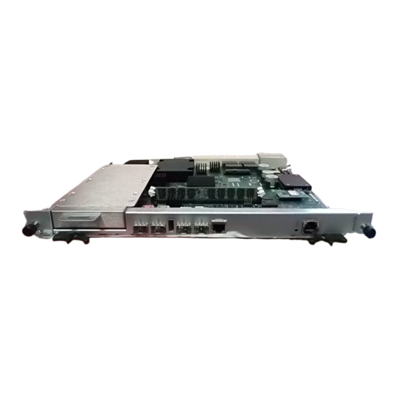
ATCA-F125
Quick Start Guide
P/N: 6806800K92D November 2019
1 Box contents
Make sure you receive all items of your shipment:
•
One ATCA-F125 blade
•
One printed copy of Quick Start Guide (this document)
•
One printed copy of Safety Notes Summary
•
Other items that were ordered
When installing or servicing the system or accessories,
strictly observe the safety precautions in the Safety Notes
Summary. Ignoring these instructions can void the system
warranty and cause personal injury or property damage.
2 ESD
Electrostatic discharge and incorrect installation or
removal of the card can damage circuit or shorten its life.
Use a properly grounded ESD wrist strap or work in an
ESD-safe environment.
Connect to the ESD connector at the front or the rear of
the system.
3 Site preparation
Make sure that all environmental and power requirements defined in
the ATCA-F125 Installation and Use manual are met.
Operating temperatures refer to the temperature of the air circulating
around the blade and not to the actual component temperature.
4 Install the SATA storage
1. Attach the standoffs to the appropriate holes in the HDD.
2. Attach the tape to the HDD making sure the vent hole of the HDD
is not covered.
3. Assemble the SATA mounting plate to the two brackets using
four M3x3 mm screws
4. Attach the brackets to the HDD using four M3x3 mm screws.
5. Install the HDD assembly and secure it from the bottom side
using the four M3x5 mm screws. Torque should be based on
manufacturer's recommendation.
5 Install the QSFP+/SFP+
modules
1. Slide the QSFP+/SFP+ module into the slot until it locks into
position.
2. Remove the optical port plug.
3. Connect the network cable to the QSFP+/SFP+ module.
6 Install the PrAMC
1. If the AMC bay is occupied by an AMC filler panel, remove it
first.
2. Make sure that the AMC module handle is in the extracted
position: pulled outward, away from the face plate.
3. Carefully slide the AMC module into the guide rails until
resistance is felt.
4. Apply equal and steady pressure on the face plate as necessary
until the module is fully engaged with the connector. Avoid using
excessive force.
5. Press the module handle inwards toward the face plate to lock
the AMC module into the AMC bay.
7 Install the blade
If a Rear Transition Module (RTM) is needed, install and
secure it first according to the RTM-ATCA-F125
Installation and Use before installing the front blade.
NOTE: The following procedure assumes that the system is
powered. If the system is unpowered, disregard the blue LED and
skip its respective step.
1. Ensure that the top and bottom ejector handles are in the
outward position by squeezing the lever and the latch
together.
2. Insert the blade into the shelf by placing the top and bottom
edges of the blade in the card guides of the shelf. Ensure that the
guiding module of the shelf and blade are aligned properly.
3. Apply equal and steady pressure to the blade to carefully slide
the blade into the shelf until you feel resistance. Continue to
gently push the blade until the blade connectors engage.
4. Squeeze the lever and the latch together. Hook the lower and the
upper handle into the shelf rail recesses.
5. Fully insert the blade and lock it to the shelf by squeezing the
lever and the latch together and turning the handles towards the
face plate. If the shelf is powered, the blue LED is illuminated as
soon as the blade connects to the backplane. When the blade is
completely installed, the blue LED will blink, indicating that the
blade is connecting to the shelf management controller.
NOTE: If the RTM is connected to the front blade, make sure that
the handles of both the RTM and the front blade are closed in order
to power up the blade's payload.
6. When the blue LED is off, tighten the face plate screws to secure
the blade to the shelf. The switched off blue LED indicates that
the blade's payload has been powered up and that the blade is
active.
7. If necessary, connect cables to the face plate.
Advertisement

Subscribe to Our Youtube Channel
Related Manuals for SMART ATCA-F125


Summary of Contents for SMART ATCA-F125
- Page 1 5. Press the module handle inwards toward the face plate to lock Make sure that all environmental and power requirements defined in the AMC module into the AMC bay. the ATCA-F125 Installation and Use manual are met. Quick Start Guide Operating temperatures refer to the temperature of the air circulating 7 Install the blade around the blade and not to the actual component temperature.
- Page 2 SMART Modular Technologies, Inc. All other names and logos referred to are trade names, trademarks, or registered trademarks of their respective owners. These materials are provided by SMART Embedded Computing as a service to its customers and may be used for informational purposes only. For full legal terms and conditions, visit www.smartembedded.com/ec/legal.
Need help?
Do you have a question about the ATCA-F125 and is the answer not in the manual?
Questions and answers