
Subscribe to Our Youtube Channel
Related Manuals for ITC Audio T-8000A

Summary of Contents for ITC Audio T-8000A
- Page 1 PUBLIC ADDRESS SYSTEM AUDIO AUDIO T-8000A 8 ZONE PAGING MIC Please follow the instructions in this manual to obtain the optimum results from this unit. We also recommend that you keep this manual handy for future reference.
-
Page 2: Table Of Contents
TABLE OF CONTENTS 1. SAFETY PRECAUTIONS ..................3 2. DESCRIPTION ....................... 5 FRONT PANEL 3. FRONT AND REAR PANEL( ..........6 4. FRONT AND REAR PANEL(REAR PANEL) ............8 5. CONNECTION AND SETTINGL ................9 6. OPERATION GUIDANCE ..................10... -
Page 3: Safety Precautions
1. SAFETY PRECAUTIONS Be sure to read the instructions in this section carefully before use. Make sure to observe the instructions in this manual as the conventions of safety symbols and messages regarded as very important precautions are included. We also recommend you keep this instruction manual handy for future reference. Safety Symbol and Message Conventions Safety symbols and messages described below are used in this manual to prevent bodily injury and property damage which could result from mishandling. - Page 4 SAFETY PRECAUTIONS When the Unit is in Use When Installing the Unit Do not place heavy objects on the unit as this may Never plug in nor remove the power supply plug cause it to fall or break which may result in with wet hands, as doing so may cause electric personal injury and/or property...
-
Page 5: Description
2.DESCRIPTION 1.The T-8000A remote zone paging microphone work together with T-8000 through universal industrial standard CAT5 cable for zone announcement or communication at a remote and different location from the control center. 2.Each matrix controller T-8000 provides two RJ45 ports for the remote paging microphone. -
Page 6: Front And Rear Panel
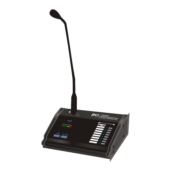
3. FRONT AND REAR PANEL FRONT PANEL 8 9 10 1. GOOSENECK MICROPHONE 2. POWER INDICATOR The LED will be light on blue when power switch is placed at on position, which will be extinguished when power switch is placed at off position. 3. - Page 7 NOMENCLATURE AND FUNCTIONS Label insert from here Length :20mm Width :6mm Distance from center to center 9mm ZONE INDICATOR Dual color indicator LED is used to display the zone status. The indicator will be illuminated on blue under paging status and on amber under busy status. 10.
-
Page 8: Front And Rear Panel(Rear Panel)
4. FRONT AND REAR PANEL REAR PANEL MIC VOL. CHIME VOL. CHIME 2 TONE 4 TONE POWER 24VDC 11. POWER SWITCH. The paging console is powered from the matrix through CAT5 cable.Power on when power switch is placed at on position, and power off when power switch is placed at off position. -
Page 9: Connection And Settingl
5. CONNECTION AND SETTING 5.1 Onnection between the remote paging console and the extension keypad: The IDE communication cable is used to provide connection between the remote paging console and the extension keypad and between two extension keypads Connection through 10P IDE cable Extension keypad Remote paging Console... -
Page 10: Operation Guidance
6.OPERATION GUIDANCE 6.1 Zone selection 6.1.1 Announcement shall be started after individual zone or all zone selection, the matrix will feedback to the remote paging console's or extension keypad's inquiry, the permission of paging or busy will be displayed as different indicator: blue and amber. 6.1.2 All call will be made to the total 8 zones if it is only for the remote paging console, and all call will be made to all the zones includes the remote paging console's and the extension keypad's when any extension keypad is existed. - Page 11 PUBLIC ADDRESS SYSTEM VersionV0.1...
Need help?
Do you have a question about the T-8000A and is the answer not in the manual?
Questions and answers