Table of Contents
Advertisement
Quick Links
Advertisement
Table of Contents

Related Manuals for TYAN YR290 B7018-D2


Summary of Contents for TYAN YR290 B7018-D2
- Page 1 YR290 B7018-D2 Service Engineer’s Manual http://www.tyan.com...
- Page 2 http://www.tyan.com...
- Page 3 Neither this manual, nor any material contained herein, may be reproduced without written consent of manufacturer. ® Copyright 2012 MiTAC International Corporation. All rights reserved. TYAN a registered trademark of MiTAC International Corporation. Version 1.2a Disclaimer Information contained in this document is furnished by MiTAC International Corporation and has been reviewed for accuracy and reliability prior to printing.
- Page 4 There will be danger of explosion if battery is incorrectly replaced. Replace only with the same or equivalent type recommended by manufacturer. Dispose of used battery according to manufacturer instructions and in accordance with your local regulations. http://www.tyan.com...
- Page 5 About this Manual This manual provides you with instructions on installing your TYAN YR290 B7018-D2. This Manual is intended for experienced users and integrators with hardware knowledge of personal computers. This manual consists of the following parts: Chapter1: Provides an introduction to the TYAN YR290...
- Page 6 SAFETY INFORMATION Before installing and using TYAN YR290 B7018-D2, take note of the following precautions: ·Read all instructions carefully. ·Do not place the unit on an unstable surface, cart, or stand. ·Do not block the slots and opening on the unit, which are provided for ventilation.
-
Page 7: Table Of Contents
Table of Contents Chapter 1: Overview ................. 9 About the TYAN YR290 B7018-D2 .......... 9 Features.................. 10 Product Model................. 15 Standard Parts List ..............16 1.4.1 Box Contents Per Node ........... 16 1.4.2 Accessories ..............18 About the Product ..............20 1.5.1... - Page 8 M7018-BP2 HDD Backplane Board Features ....65 3.7.2 M7018-BP2 Connector Pin Definitions ......66 Replacing the Power Supply..........68 Appendix I: Cable Connection Tables .......... 69 (TYAN Proprietary Design) ............73 Appendix II: FRU Parts Table ............73 Appendix III: Technical Support............ 75 http://www.tyan.com...
-
Page 9: Chapter 1: Overview
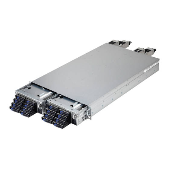
® TYAN also offers the YR290 B7018-D2 in a version that can support up to sixteen hot-swap hard drives (eight per node). The YR290 B7018-D2 uses latest chassis designs which features a solid mechanical enclosure and robust features. -
Page 10: Features
Features TYAN YR290 B7018-D2 (B7018Y290D2-045W8HR) Form Factor 2U Rackmount Frame w/ 2x 2U Blades Chassis Model YR290 Dimension (D x W x 28.74" x 17.32" x 3.44" (730 x 440 x 87.5mm) Blade Dimension 28.74" x 8.46" x 3.32" (730 x 214.8 x 84.5mm) - Page 11 Port Q'ty Total (3) ports, (1) dedicated for IPMI LAN (per blade) Controller Intel 82576EB / Intel 82574L (2) Mini-SAS connectors (totally support 8 ports), Connector from TYAN P3202 storage adapter card Controller LSI 1068E Speed 3.0 Gb/s Storage (per RAID...
- Page 12 RoHS Complaint (1) Quick Ref. Guide / (1) MB User's manual + (1) Manual BB User's manual Installation CD (1) TYAN installation CD Package Heatsink / Cooler (4) LGA1366 CPU heatsinks Contains Rail kit (1) sliding rail kit for YR290...
- Page 13 Capacity Up to 96GB RDIMM / 48GB UDIMM Memory channel 3 Channels per CPU Memory voltage 1.5V PCI-E (1) PCI-E Low-Profile Gen.2 x16 slot Pre-install TYAN Expansion M7018-R16-2F1L, 2U PCI-E x16 riser card (right) Riser Card Slots (per Max. HBA blade) (2) 111.15mm x 312.00mm (FH/FL) / (1) 68.90mm x...
- Page 14 CE (DoC) Operating Temp. 10° C ~ 35° C (50° F~ 95° F) Non-operating Operating - 40° C ~ 70° C (-40° F ~ 158° F) Temp. Environment In/Non-operatin 90%, non-condensing at 35° C g Humidity RoHS 6/6 RoHS Complaint http://www.tyan.com...
-
Page 15: Product Model
(1) Quick Ref. Guide / (1) MB User's manual + (1) BB Manual User's manual Installation CD (1) TYAN installation CD Package Heatsink / (4) LGA1366 CPU heatsinks Contains Cooler Rail kit (1) sliding rail kit for YR290 Power (2) CCBL-0310, US type power cord / (2) CCBL-0300,... -
Page 16: Standard Parts List
Standard Parts List This section describes the YR290 B7018-D2 package contents and accessories. Open the box carefully and ensure that all components are present and undamaged. The product should arrive packaged as illustrated below. 1.4.1 Box Contents Per Node (SATA Interface) - Page 17 M7018-R16-1F1YR1L PCI-E Riser Card (pre-installed) NOTE: The 2 PCI-E slot is a proprietary slot for the TYAN P3202 SAS card ONLY. The use of any other PCI-E card could result in damage to the M7018 Riser card or party PCI-E card directly.
-
Page 18: Accessories
AC Power Cord 250V (US) (Europe) Barebone Manual Mainboard Manual NOTE: The TYAN Driver CD does not contain the P3202 LSI 1068E 3G SAS HBA driver. To obtain the driver for LSI 1068E, please visit the LSI Web site at http://www.lsi.com/storage_home/products_home/standard_product_i cs/sas_ics/lsisas1068e/index.html?remote=1&locale=EN http://www.tyan.com... - Page 19 Ultra-slim DVD-ROM DVD Bracket DVD-ROM Screw Pack Rail Kit Rail x2 Screw Pack http://www.tyan.com...
-
Page 20: About The Product
Activity LED: blinking green HDD activity Fault LED: Off Activity LED: Off HDD Fail Fault LED: Red Activity LED: random Identify Fault LED: blinking red @ 4 Hz Activity LED: random Rebuild Fault LED: blinking red @ 1 Hz http://www.tyan.com... - Page 21 Press the ID (UID) button once and the dual-color Power LED on the front panel and the blue ID LED 7. ID (UID) on the rear panel will turn blue. Press the button again to stop. 8. Reset Press to reset the system http://www.tyan.com...
-
Page 22: System Rear View (Per Node)
Left: slow blinking green 100 Mbps Link Right: green Left: blinking green 100 Mbps Activity Right: green Left: slow blinking green 1000 Mbps Link Right: amber Left: blinking green 1000 Mbps Activity Right: amber Left: Off No Link Right: Off http://www.tyan.com... -
Page 23: Internal View (Per Node)
1.5.3 Internal View (Per Node) Number Description HDD Cage M7018-BP2 SATA/SAS HDD Backplane Board System Fans Power Distribution Board PCI-E Riser Card Assembly Air Duct CPU Sockets Memory Slots http://www.tyan.com... - Page 24 NOTE http://www.tyan.com...
-
Page 25: Chapter 2: Setting Up
A grounding strap or an anti-static pad Most of the electrical and mechanical connections can be disconnected with your hands. It is recommended that you do not use pliers to remove connectors as it may damage the soft metal or plastic parts of the connectors. http://www.tyan.com... -
Page 26: Precautions
Metallic parts or metal flakes can cause electrical shorts. NOTE: All connectors are keyed to only attach one way. All use the correct screw size as indicated in the procedures. http://www.tyan.com... -
Page 27: Installing Motherboard Components
Installing the DVD-ROM Drive (Optional) Follow these instructions to install a DVD-ROM drive. Push the ultra-slim DVD-ROM drive holder out. Prepare a DVD-ROM bracket and two DVD screws to secure the bracket to the rear of the DVD-ROM drive. http://www.tyan.com... - Page 28 Insert the DVD-ROM drive into the chassis. http://www.tyan.com...
- Page 29 Connect the SATA cable and DVD power cable to the DVD-ROM drive. NOTE: The illustration is based on a SAS Interface system. Thus, the connector marked is left idle. http://www.tyan.com...
- Page 30 B4P for MB J15 → ODD PWR Cable S4P for Riser J4 SATA3 (JP2) for → SATA Cable NOTE: If a DVD-ROM drive is installed into a SATA SKU, a single node can support a maximum of 3 Hard Disk drives. http://www.tyan.com...
-
Page 31: Installing The Cpu And Heatsink
Installing the CPU and Heatsink Follow the steps below to install the processor and heatsink. Locate the CPU socket. Push the CPU lever slightly away from the socket to unlock the socket. Pull the lever to a fully open position. http://www.tyan.com... - Page 32 Push to fully open the socket cover. Remove the protection cap. http://www.tyan.com...
- Page 33 Place the CPU in the CPU socket. Close the socket cover and press the CPU socket lever down to secure the CPU. http://www.tyan.com...
- Page 34 Place the heatsink on top of the CPU and secure it with 4 screws. Repeat the procedures described earlier to install the second CPU. http://www.tyan.com...
-
Page 35: Installing The Memory
Press the memory slot locking levers in the direction of the arrows as shown in the following illustration. Align the memory module with the slot. When inserted properly, the memory slot locking levers lock automatically onto the indentations at the ends of the module. http://www.tyan.com... - Page 36 DIMM B0 x(*) DIMM B1 x(*) DIMM A0 x(*) DIMM A1 x(*) Max Memory combination Single Rank Unbuffered DIMMs 24GB(12x2GB DIMMs) Dual Rank Unbuffered DIMMs 48GB(12x4GB DIMMs) NOTE: X(*) represents max speed of 1066Mhz if installed in this configuration. http://www.tyan.com...
- Page 37 Single Rank Registered DIMMs 48GB(12x4GB DIMMs) Dual Rank Registered DIMMs 96GB(12x8GB DIMMs) Quad Rank Registered DIMMs 96GB(12x8GB DIMMs) NOTE: X(*) represents max speed of 1066MHz if installed in this configuration. X(**) represents max speed of 800MHz if installed in this configuration. http://www.tyan.com...
-
Page 38: Rack Mounting
Follow these instructions to mount the TYAN YR290 B7018-D2 into an industry standard 19” rack. NOTE: Before mounting the TYAN YR290 B7018-D2 in a rack, ensure that all internal components have been installed and that the unit has been fully tested. -
Page 39: Installing The Inner Rails To The Chassis
2.2.2 Installing the inner Rails to the Chassis Draw out the inner rails from the rail assembly. Install inner rails to the left and right side of chassis. Push the rails forwards to lock the rails in place. http://www.tyan.com... -
Page 40: Installing The Outer Rails To The Rack
/ 2 sets rear) for each side. Secure the rails to the rack as shown. Repeat Step 2 if you want to install more chassis to the rack. To make the installation easier, we suggest that you remove all nodes before you insert the chassis to the rack. http://www.tyan.com... -
Page 41: Rack Mounting The Server
2.2.4 Rack mounting the Server To install the chassis to the rack Lift the chassis and then insert the inner slide rails into the outside rails. Push the chassis back into the rack. http://www.tyan.com... - Page 42 Screw the chassis to the rack. Insert the node into the chassis. Repeat Step 4 for the second node. http://www.tyan.com...
- Page 43 Always install the hard disk drive to the chassis after the chassis is secured on the rack. The YR290 B7018-D2 supports up to (8) 2.5” hard drives per node. Follow these instructions to install a hard drive. Press the locking lever latch and pull the locking lever open.
- Page 44 Unscrew the HDD tray bracket. Place a hard drive into the drive tray. Use four screws to secure the HDD. Reinsert the HDD tray into the chassis. http://www.tyan.com...
- Page 45 Press the locking lever to secure the tray. Repeat the same procedures to install other HDD trays. http://www.tyan.com...
- Page 46 Press the locking tabs on both sides of the chassis to pull the chassis out. NOTE: To avoid injury, it is strongly recommended that two people lift the TYAN YR290 B7018-D2 into the place while a third person screws it to the rack. http://www.tyan.com...
-
Page 47: Chapter 3: Replacing Pre-Installed Components
Motherboard, M5376 front panel board, M7018-BP2 SATA/SAS HDD Backplane Board, M7018-R16-2F1L (SATA Interface) or M7018-R16-1F1YR1L (SAS Interface) PCI-E Riser card, System fans, and Power supply unit, etc. Disassembly Flowchart The following flowchart outlines the disassembly procedure. Rear Components Node DIMMs Power CPU/Heatsink Assembly PCI-E Card Mainboard Mainboard http://www.tyan.com... - Page 48 Front Components Node PCBs Front Panel SATA/SAS HDD Board Backplane http://www.tyan.com...
-
Page 49: Replacing Motherboard Components
NOTE: The 2 PCI-E slot on the M7018 R16-1F1YR1L PCIe Riser Card is a proprietary slot for the TYAN P3202 SAS card ONLY. The use of any other PCI-E card could result in damage to the M7018 R16-1F1YR1L PCIe Riser Card... - Page 50 Unscrew to remove the PCI-E bracket. Install a PCI-E card onto the assembly. Screw the PCI-E card back to the assembly. Repeat Step 3 & 4 to install a low-profile PCI-E card. http://www.tyan.com...
- Page 51 NOTE: The following illustration is based on a M7018-R16-1F1YR1L riser card. The card actually installed in your system may be different from the illustration. Follow the procedures mentioned earlier in reverse order to place the riser card assembly back into the chassis. http://www.tyan.com...
-
Page 52: Disconnecting All Motherboard Cables
3.3.2 Disconnecting All Motherboard Cables Before replacing the motherboard or certain components, remove cables connected to the motherboard. Follow these instructions to remove all motherboard cables. Unplug all cables connected to the mainboard. (Power) (PSMI) (Fan) http://www.tyan.com... - Page 53 (Front Panel and USB) http://www.tyan.com...
-
Page 54: Removing The Motherboard
After removing all of the aforementioned cables, follow the instructions below to remove the motherboard from the chassis. Remove the heatsink and processor if installed. Remove the ten screws securing the motherboard to the chassis. Carefully lift the motherboard from the chassis. http://www.tyan.com... -
Page 55: Replacing The Power Distribution Board
→ PSMI Cable (J39) PDB to S7018 MB Connect to S7018 MB → 2x10P PWR Cable MB 2X10P Conn (J14) PDB to SATA/SAS BP Board Connect to SATA/SAS BP Board HDD BP 2X4 Conn → 2x4P PWR Cable (PW1) http://www.tyan.com... - Page 56 Unscrew to take out the power distribution board. After replacing a new power distribution board, repeat the procedures described earlier in reverse order to put the new set back in place. http://www.tyan.com...
-
Page 57: Replacing The Front Panel Board
Replacing the Front Panel Board Follow these instructions to replace the Front Panel board. Unplug two front panel cables. FPB to SATA/SAS BP SATA/SAS BP Cable Connect to Board → Control Cable Unscrew the front panel tray. http://www.tyan.com... - Page 58 Pull the front panel tray from the chassis. Disconnect the Front Panel Control and USB cables from the front panel board. Front Panel Board (FPB) to S7018 MB Cable Connect to S7018 MB Front Panel Conn → Control Cable (J23) → USB Cable USB2 Conn (J11) http://www.tyan.com...
- Page 59 Unscrew to take out the front panel board. Replace a new front panel board and screw it to the front panel tray. Repeat the procedures described earlier in reverse order to place the front panel tray back into place. http://www.tyan.com...
-
Page 60: Front Panel Board Features
1 VCC_USB0 Power connect to 5V (for USB) 6 USB_P1_P USB_P1 + 2 VCC_USB1 Power connect to 5V (for USB) 7 GND Ground 3 USB_P0_N USB_P0 - 8 GND Ground 4 USB_P1_N USB_P1 - 9 NC 5 USB_P0_P USB_P0 + 10 NC http://www.tyan.com... -
Page 61: Replacing The System Fan
Loose the screws that secure the fans to the chassis. Lift the fans up. NOTE: To replace a single fan, just loose the screws which go with the fan. For example, FAN 1 goes with Screw 1 and 4. Use your fingers to pull the rubber screws out. http://www.tyan.com... - Page 62 Reinstall the fans into the chassis following the procedures described earlier in reverse order. Connect the fan cables to the motherboard. System Fan to S7018 MB System Fan Connect to S7018 MB → Fan1 → Fan2 → Fan3 http://www.tyan.com...
-
Page 63: Replacing The M7018-Bp2 Hdd Backplane Board
3.6 Replacing the System Fans to lift the fans up. Disconnect all cables from the M7018-BP2 SATA backplane board. (2 Mini SAS + 1 FP) FPB to SATA/SAS BP SATA/SAS BP Cable Connect to Board → Control Cable (1 8-pin Power) http://www.tyan.com... - Page 64 Mini-SAS Cable-3 SATA1 (JP4) → Mini SAS1 (36P to 4x7P) SATA2 (JP3) SATA3 (JP2) Unscrew the backplane bracket to lift it up from the chassis. Reinstall a new M7018-BP2 Backplane Board into the chassis following the above steps in reverse. http://www.tyan.com...
-
Page 65: M7018-Bp2 Hdd Backplane Board Features
3.7.1 M7018-BP2 HDD Backplane Board Features http://www.tyan.com... -
Page 66: M7018-Bp2 Connector Pin Definitions
PIN B18 SAS_RX7+ SAS_RX7- PIN B8 PIN B9 PIN B10 PIN A9 SGPIO_DOUT_B SGPIO_END_B PIN A10 PIN A11 PIN B11 PIN A8 SGPIO_DIN_B SGPIO_CLK_B PIN G1 PIN G2 PIN G3 PIN G4 PIN G5 PIN G6 PIN G7 PIN G8 http://www.tyan.com... - Page 67 PIN B18 SAS_RX3+ SAS_RX3- PIN B8 PIN B9 PIN B10 PIN A9 SGPIO_DOUT_A SGPIO_END_A PIN A10 PIN A11 PIN B11 PIN A8 SGPIO_DIN_A SGPIO_CLK_A PIN G1 PIN G2 PIN G3 PIN G4 PIN G5 PIN G6 PIN G7 PIN G8 http://www.tyan.com...
-
Page 68: Replacing The Power Supply
Replacing the Power Supply 1. Press and hold the latch to pull the power supply out. 2. After replacing a new power supply, press and hold the latch to push the power supply back into the chassis. http://www.tyan.com... -
Page 69: Appendix I: Cable Connection Tables
SAS Port2 (J2) (36P to 36P) SATA/SAS Backplane (BP) Board to S7018 MB (for SATA interface) SATA/SAS BP Cable Connect to S7018 MB Board SATA0 (JP5) Mini-SAS Cable-3 SATA1 (JP4) → Mini SAS1 (36P to 4x7P) SATA2 (JP3) SATA3 (JP2) http://www.tyan.com... - Page 70 HDD BP 2X4 Conn → 2x4P PWR Cable (PW1) Riser Card to S7018 MB(For SATA interface) Cable Riser Card Connect to S7018 → B4P to S4P Cable PDB to S7018 MB Cable Connect to S7018 M/B PSMI Conn → PSMI Cable (J39) http://www.tyan.com...
- Page 71 B4P for MB J15 → ODD PWR Cable S4P for Riser J4 SATA3 (JP2) for → SATA Cable NOTE: If a DVD-ROM drive is installed into a SATA SKU, a single node can support a maximum of 3 Hard Disk drives. http://www.tyan.com...
- Page 72 NOTE http://www.tyan.com...
-
Page 73: (Tyan Proprietary Design)
M7018-R32-2F1L 541178820021 M7018-R32-2F1L 2U Riser Card PCBA M7018-R16-1F1YR1L 2U Riser M7018-R16-1F1YR1L541178820019 Card P3202 8-port SAS 3.0G HBA w/ tall bracket (TYAN Proprietary P3202 541178820018 design for use only with the M7018-R16-1F1YR1L riser card) SATA Mini-SAS cable (onboard CCBL-067T 422788200006 SATA ... - Page 74 NOTE http://www.tyan.com...
-
Page 75: Appendix Iii: Technical Support
MiTAC serves multiple market segments with the industry’s most competitive services to support them. TYAN's tech support is some of the most impressive we've seen, with great response time and exceptional organization in general.” — Anandtech.com Please feel free to contact us directly for this service at tech-support@tyan.com... - Page 76 Return Merchandise Authorization (RMA) number. The RMA number should be prominently displayed on the outside of the shipping carton and the package should be mailed prepaid. TYAN will pay to have the board shipped back to you. ® TYAN YR290 B7018-D2 Service Engineer’s Manual V1.2...
Need help?
Do you have a question about the YR290 B7018-D2 and is the answer not in the manual?
Questions and answers