Download Print this page

Advertisement

Quick Links

Chipsmall Limited consists of a professional team with an average of over 10 year of expertise in the distribution
of electronic components. Based in Hongkong, we have already established firm and mutual-benefit business
relationships with customers from,Europe,America and south Asia,supplying obsolete and hard-to-find components
to meet their specific needs.
With the principle of "Quality Parts,Customers Priority,Honest Operation,and Considerate Service",our business
mainly focus on the distribution of electronic components. Line cards we deal with include
Microchip,ALPS,ROHM,Xilinx,Pulse,ON,Everlight and Freescale. Main products comprise
IC,Modules,Potentiometer,IC Socket,Relay,Connector.Our parts cover such applications as commercial,industrial,
and automotives areas.
We are looking forward to setting up business relationship with you and hope to provide you with the best service
and solution. Let us make a better world for our industry!
Contact us
Tel: +86-755-8981 8866 Fax: +86-755-8427 6832
Email & Skype: info@chipsmall.com Web: www.chipsmall.com
Address: A1208, Overseas Decoration Building, #122 Zhenhua RD., Futian, Shenzhen, China
  

Advertisement

loading
Need help?

Need help?

Do you have a question about the Inventor's Kit and is the answer not in the manual?

Questions and answers

Summary of Contents for sparkfun Inventor's Kit

  • Page 1 Chipsmall Limited consists of a professional team with an average of over 10 year of expertise in the distribution of electronic components. Based in Hongkong, we have already established firm and mutual-benefit business relationships with customers from,Europe,America and south Asia,supplying obsolete and hard-to-find components to meet their specific needs.
  • Page 2 SparkFun Inventor ’ s Kit V E R S I O N 4 . 0 a Your Guide to the SIK for the SparkFun RedBoard...
  • Page 3 This is your map for navigating beginning embedded electronics. This booklet contains all the information you will need to build five projects encompassing the 16 circuits of the SIK for the SparkFun RedBoard. At the center of this manual is one core philosophy: that anyone can (and should) play around with electronics.
  • Page 4 Contents INTRODUCTION 2 The RedBoard Platform 3 Baseplate Assembly 4 RedBoard Anatomy 5 Breadboard Anatomy 6 The Arduino IDE 10 Inventory of Parts PROJECT 1: LIGHT 13 Circuit 1A: Blinking an LED 20 Circuit 1B: Potentiometer 26 Circuit 1C: Photoresistor 31 Circuit 1D: RGB Night-Light PROJECT 2: SOUND 37 Circuit 2A: Buzzer...
  • Page 5 THE SPARKFUN REDBOARD is one of a multitude of development boards based on the ATmega328 microprocessor. It has 14 digital input/output pins (six of which can be PWM outputs), six analog inputs, a 16MHz crystal oscillator, a USB connection, a power jack, and a reset button.
  • Page 6 Baseplate Assembly Before you can build circuits, you’ll want to first assemble the breadboard baseplate. This apparatus makes circuit building easier by keeping the RedBoard microcontroller and the breadboard connected without the worry of disconnecting or damaging your circuit. TO BEGIN, collect your parts: the RedBoard, breadboard, included screwdriver, baseplate and two baseplate screws.
  • Page 7 Anatomy of the SparkFun RedBoard RESET DIGITAL (PWM~) S T A R T S O M E T H I N G POWER ANALOG IN REDBOARD HARDWARE OVERVIEW P O W E R I N Can be used with either a 9V or 12V “wall-wart” or a battery pack.
  • Page 8 Anatomy of the Breadboard A breadboard is a circuit-building platform that allows you to connect multiple components without using a soldering iron. H O R I Z O N TA L R O W S P O W E R B U S Each series of 5 sockets marked Each side of the breadboard has a pair of a–e and f–j are connected.
  • Page 9 2. INSTALL USB DRIVERS In order for the RedBoard hardware to work with your computer’s operating system, you will need to install a few drivers. Please go to www.sparkfun.com/FTDI for specific instructions on how to install the USB drivers onto your computer.
  • Page 10 4. DOWNLOAD AND INSTALL THE SIK CODE Each of the circuits you will build in the SparkFun Inventor’s Kit has an Arduino code sketch already written for it. This guide will show you how to manipulate that code to control your hardware.
  • Page 11 5. OPEN THE ARDUINO IDE: Open the Arduino IDE software on your computer. Poke around and get to know the interface. We aren’t going to code right away; this step is to set your IDE to identify your RedBoard. Blink | Arduino 1.8.5 Blink T H E T H R E E M O S T I M P O R TA N T...
  • Page 12 6. SELECT YOUR BOARD AND SERIAL DEVICE NOTE: Your SparkFun RedBoard and the Arduino/Genuino UNO are interchangeable, but you won’t find the RedBoard listed in the Arduino software. Select “ARDUINO/GENUINO UNO” instead. Sketch Tools Help Auto Format Archive Sketch Fix Encoding and Reload...
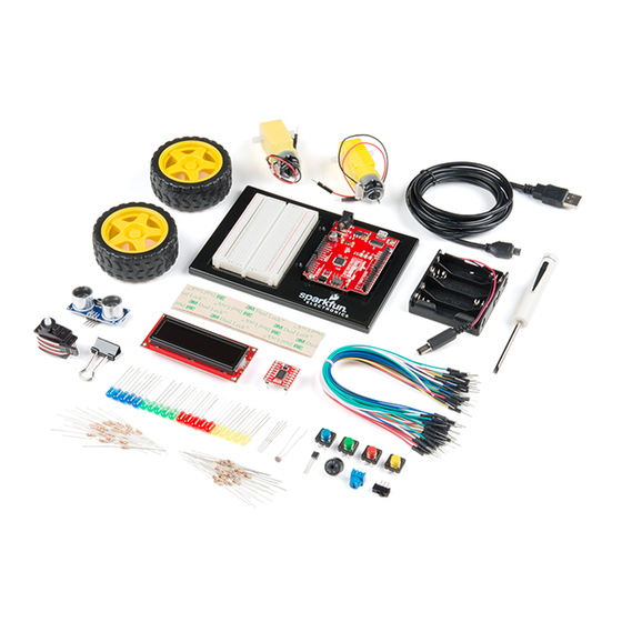
  • Page 13 Inventory of Parts The SparkFun Inventor’s Kit contains an extensive array of electronic components. As you work your way through each circuit, you will learn to use new and more complicated parts to accomplish increasingly complex tasks. L E D S...
  • Page 14 Let’s Get Started With Your First Circuit! 1 1 : I N T R O...
  • Page 15 P H O T O R E S I S T O R PROJECT 1 NEW IDEAS Welcome to your first SparkFun Inventor’s Kit Each project will introduce new project. Each project is broken up into several concepts and components, which will...
  • Page 16 You can find LEDs in just about any source Circuit 1A: of light, from the bulbs lighting your home Blinking an LED to the tiny status lights flashing on your home electronics. Blinking an LED is the classic starting point for learning how to program embedded electronics.
  • Page 17 NEW IDEAS ELECTRICAL SAFETY: Never work on your circuits while the board is connected to a power source. The SparkFun RedBoard operates at 5 volts, which, while not enough to injure you, is enough to damage the components in your circuit.
  • Page 18 HOOKUP GUIDE READY TO START HOOKING EVERYTHING UP? Check out the circuit diagram and hookup table below to see how everything is connected. F L AT E D G E – – 7-15V AREF IOREF RESET 3.3V CIRCUIT DIAGRAMS: Each circuit contains a circuit diagram, which acts as a visual aid designed to make it easier for you to see how your circuit should be built.
  • Page 19 Open the Arduino IDE Connect the RedBoard to a USB port on your computer. Open the Sketch: File > Examples > SIK_Guide_Code-V_4 > CIRCUIT_1A-BLINK Select UPLOAD to program the sketch on the RedBoard. duino File Edit Sketch Tools Help Open Open Recent Sketchbook Examples...
  • Page 20 PROGRAM OVERVIEW Turn the LED on by sending power (5V) to digital pin 13. Wait 2 seconds (2000 milliseconds). Turn the LED off by cutting power (0V) to digital pin 13. Wait 2 seconds (2000 milliseconds). Repeat. ONBOARD LED PIN 13: You may have noticed a second, smaller LED blinking in unison with the LED in your breadboard...
  • Page 21 CODE TO NOTE DIGITAL OUTPUT: When you’re using a pin as an OUTPUT, you can command it to be HIGH (output 5 volts) or LOW (output 0 volts). digitalWrite(D13, HIGH); Causes the program to wait on this line of code for the amount of DELAY: time in between the brackets, represented in milliseconds (2000ms = 2s).
  • Page 22 TROUBLESHOOTING If you’re sure you have the correct Board selected but you still can’t I still get an error when upload, check that you have selected the correct serial port. You can uploading my code change this in Tools > Serial Port > your_serial_port. Depending on how many devices you have plugged into your computer, you may have several active serial ports.
  • Page 23 of the knob with your RedBoard, you can Circuit 1B: make volume controls, speed controls, Potentiometer angle sensors and a ton of other useful inputs for your projects. In this circuit, you’ll use a potentiometer as an input Potentiometers (also known as “trimpots” device to control the speed at which your or “knobs”) are one of the basic inputs for LED blinks.
  • Page 24 HOOKUP GUIDE READY TO START HOOKING EVERYTHING UP? Check out the circuit diagram and hookup table below to see how everything is connected. F L AT E D G E – – 7-15V AREF IOREF RESET 3.3V – – NEW IDEAS POTENTIOMETERS are not polarized and can be installed in either direction.
  • Page 25 Open the Arduino IDE Connect the RedBoard to a USB port on your computer. Open the Sketch: File > File > Examples > SIK_Guide_Code-V_4 > CIRCUIT_1B-POTENTIOMETER Select UPLOAD to program the sketch on the RedBoard. W H A T Y O U S H O U L D S E E You should see the LED blink faster or slower in accordance with your...
  • Page 26 ARDUINO PRO TIP ARDUINO SERIAL MONITOR: The Blink | Arduino 1.8.5 Serial Monitor is one of the Arduino IDE’s Serial Monitor Blink many great included features. When working with embedded systems, it helps to see and understand the values that your program is trying to work with, and it can be a powerful debugging tool when you run into issues where your code is not...

This manual is also suitable for:

Sik