
Related Manuals for Positron BRX-VDSL2


Summary of Contents for Positron BRX-VDSL2
- Page 1 BRX-VDSL2 Broadband Reach eXtender – VDSL2 User Guide March 2018 BRX-VDSL2 User Guide 180-0153-001-R02...
- Page 2 Product names, other than Positron's, mentioned herein may be trademarks and/or registered trademarks their respective owners. Disclaimer Notice Although Positron Access Solutions Corp. has made every effort to ensure the accuracy of the information contained herein, this document is subject to change. BRX-VDSL2 User Guide...
- Page 3 Regulatory Compliance and Safety FCC Declaration of Conformance All of the BRX-VDSL2 models (includes BRX-VDSL2-X models) comply with part 15 class A of the FCC Rules. Operation is subject to the following two conditions (1) This device may not cause harmful interference, and (2) this device must accept any interference received, including interference that may cause undesired operation.
- Page 4 Le BRX-24S est conforme aux normes Precautions and warnings Always use a circuit that provides POTS sealing current to the copper pair to power a BRX-VDSL2 unit. When deploying a BRX-VDSL2 on a copper pair without sealing current, always make sure to use power injector devices approved by Positron Access Solutions for that use.
- Page 5 The equipment must be connected to a protective ground in accordance with the instructions provided in this manual. Always ensure that BRX-VDSL2 units are connected to a chassis ground path of 25 ohms or less to avoid damage to the equipment from lightning strikes and other electrical surges.
-
Page 6: Table Of Contents
Table of Contents General Description ......................6 BRX-VDSL2 Main Advantages ..................7 Bandwidth Performance and Placement Flexibility ............7 Expected Bandwidth Improvement with BRX-VDSL2 and BRX-VDSL2-X ......7 BRX-VDSL2 Placement Flexibility ..................9 Optimum Placement......................10 BRX-VDSL2 Calculator ...................... 11 Miscellaneous Other Placement Guidelines .............. -
Page 7: General Description
General Description The Broadband Reach eXtender – VDSL2 (BRX-VDSL2) is a fully integrated solution that increases the bandwidth and/ or extends the reach of DSLAMs or MSANs to deliver higher bandwidth services to underserved or unserved markets. For example, it extends the reach of a 25 Mbps downstream / 3 Mbps upstream service from 4,000 feet (1.2 km) to 6,000 feet (1.8 km) on 24 AWG... -
Page 8: Brx-Vdsl2 Main Advantages
Bandwidth Performance and Placement Flexibility 3.1 Expected Bandwidth Improvement with BRX-VDSL2 and BRX-VDSL2-X Both versions of the BRX-VDSL2 automatically adapt their operation to the actual line conditions to optimize performance. They provide gain amplification of the signal in the downstream (D1 and D2 bands) and upstream (U0 and U1 bands) direction making sure that the amplified signal is always within the acceptable spectrum mask and signal strength allowed by the VDSL2 standards. - Page 9 The graph below illustrates the amplified downstream bandwidth resulting from the use of BRX- VDSL2 and BRX-VDSL2-X devices compared to the non-amplified (raw) bandwidth (24 AWG / 0.51mm copper gauge) with profile 17a in Non-Vectored mode. Profiles 8a, 8b and 8d achieve very similar bandwidth amplification results.
-
Page 10: Brx-Vdsl2 Placement Flexibility
For instance, on a 24 AWG (0.51mm) loop of 6000 feet / 1.8 km, placing the BRX-VDSL2 anywhere between 3000 feet / 0.9 km and 3750 feet / 1.15 km (2750 feet / 0.84 km and 3750 feet / 1.15 km) away from the DSLAM will deliver a 25 / 4 Mbps service to the customer. -
Page 11: Optimum Placement
45-60% of the total loop distance (away from the DSLAM). 3.3 Optimum Placement Although the placement of BRX-VDSL2 devices is flexible, the curves in section 3.2 above demonstrate that there is value in properly planning the placement to optimize performance. The following curve demonstrates the optimum placement of the BRX-VDSL2 relative to total loop length. -
Page 12: Brx-Vdsl2 Calculator
3.4 BRX-VDSL2 Calculator To view the impact related to the installation of a BRX-VDSL2 unit on a given loop whether it is a 26 AWG (0.40mm), 24 AWG (0.51mm) or a 22 AWG (0.64mm) copper pair, a Windows application tool is available. -
Page 13: Miscellaneous Other Placement Guidelines
Calculator. This may be caused by a number of factors. One of the most likely reason is that the Target SNR default value in the BRX-VDSL2 Calculator (default set to 8 dB), is not the same as the one provisioned in the DSLAM. If that is the case, change the value in the Target SNR box to match the DSLAM setting. - Page 14 In addition, a red warning will pop up if the Total Loop Length is less than 4000 feet (1.2 km) or more than 8,000 feet (2.4 km) for the BRX-VDSL2 or 10,000 feet (3.0 km) for the BRX-VDSL2-X. It is important to note that the product is still operational but the amplification results will not be optimal outside of the recommended operating range.
-
Page 15: Technical Specifications
ITU-T G.992.3 ADSL2 Annex A ITU-T G.992.1 ADSL Annex A PSD Mask Compliant with ANSI T1.413 and ETSI TS 101 830-1 BRX-VDSL2: Maximum is 250 mW per pair BRX-VDSL2-X: Maximum is 650 mW per pair Power Draw Regulatory Compliance UL/CSA, FCC part 15 Class A 2/10 μsec, 1 kA... -
Page 16: Packaging Information And Port Density
In areas where more than 2 pairs need amplification, an 8-pair and a 24-pair enclosure can be used. 5.2 BRX-VDSL2 8-pair packaging The BRX-VDSL2-8 / BRX-VDSL2-X-8 comes equipped with an IP65 enclosure that houses four (4) two-pair modules (as per image on the right below) for a total of eight (8) subscriber loops. Each BRX-VDSL2-M / BRX-VDSL2-X-M card has solid-state primary lightning protection for both pairs. -
Page 17: Brx-Vdsl2 24-Pair Packaging
1-pair and 2-pair BRX-VDSL2 enclosures described above (figure 8). 5.3 BRX-VDSL2 24-pair packaging The BRX-VDSL2-24 / BRX-VDSL2-X-24 comes equipped with an IP65 enclosure that houses up to twelve (12) two-pair modules using the BRX-24S shelf (as per image on the right below) for a total of twenty-four (24) subscriber loops. - Page 18 (figure 13). The Emerson CAD-12 pedestal can also be fitted with two (2) BRX-24S to amplify up to 48 pairs when you select the BRX-VDSL2-48- 1SXPF (or BRX-VDSL2-X-48-1SXPF) version as per figure 14. Please refer to the BRX Product Selection Guide for more details.
-
Page 19: Installation And Operating Guidelines
6 Installation and Operating Guidelines 6.1 General Requirements for the Outside Plant (OSP) The BRX-VDSL2 devices are designed to be installed and operated as per the same guidelines and standard operating procedures used for typical VDSL2 loops. Qualify/Condition the Line: the copper loops must be qualified and conditioned for VDSL2 installations according to standard operator guidelines ... -
Page 20: Pots / Voice Lines
Outside Plant (OSP). When using a BRX-VDSL2-X version of the device, you will need to install a Positron BRX Power Injector to allow for proper POTS (dial tone) operation on the pair amplified by the BRX-VDSL2-X device if support for a POTS dial tone is required. - Page 21 DSLAM or the Central Office (CO). This is illustrated by Figure 16 below: Figure 16: Using Sealing Current to power the BRX-VDSL2 The BRX-VDSL2 devices can also be powered from a Positron BRX Power Injector providing the required -48Vdc sealing current via the POTS combiner circuitry of the DSLAM. This is illustrated...
-
Page 22: Installation Procedure
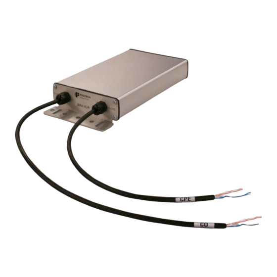
7.2 Overview of the BRX-VDSL2 / BRX-VDSL2-X-2 enclosure The BRX-VDSL2-2 / BRX-VDSL2-X-2 is a standalone unit enclosed in an IP65/NEMA 4 weather resistant enclosure. Please refer to the diagram below for a summary of the device. Note: the BRX-VDSL2 -1 / BRX-VDSL2-X-1 shares the same enclosure and installation instructions as the 2-pair BRX-VDSL2 devices. -
Page 23: Overview Of The Brx-Vdsl2-8 / Brx-Vdsl2-X-8 Enclosure
7.3 Overview of the BRX-VDSL2-8 / BRX-VDSL2-X-8 enclosure The BRX-VDSL2-8 / BRX-VDSL2-X-8 supports up to 4 BRX-VDSL2 modules enclosed in an IP65 / NEMA 4 weather resistant enclosure. Please refer to the diagram below for a summary of the device. -
Page 24: Step-By-Step Installation Instructions
Step 5: connect the corresponding CPE pair to the pair toward the subscriber home In steps 4 and 5, when connecting the pairs of the BRX-VDSL2 device, care should be taken to match the pair numbers as per the color codes in the tables of step 3 above. - Page 25 TIP11 RING11 TIP12 RING12 TIP13 RING13 TIP14 RING14 TIP15 RING15 TIP16 RING16 TIP17 RING17 TIP18 RING18 TIP19 RING19 TIP20 RING20 TIP21 RING21 TIP22 RING22 TIP23 RING23 TIP24 RING24 TIP25 RING25 Table 8: BRX-24S RJ21 (Amphenol) pin-out BRX-VDSL2 User Guide 180-0153-001-R02...
- Page 26 In this case, insert a metallic or plastic strap into the rectangular slot (0.2” by 0.8” / 5 mm by 20.3 mm) in the mounting flange at both ends of the BRX-VDSL2 enclosure and secure around the pole as per the diagrams below.
- Page 27 When using the BRX-STRAND-K, use the supplied nuts and bolts to affix the strand mount bracket into the circular slots in the mounting flange at both ends of the 1-pair, 2-pair or 8-pair BRX-VDSL2 enclosure as per the diagrams below. You can use any of the slots to adjust the strand mount bracket to clear any cables or devices already present.
-
Page 28: Splicing Pairs
7.6 Splicing Pairs When installing a BRX-VDSL2 device, it is important to follow the proper technique to ensure your safety and a good quality splice. You should follow the standard splicing Method and Procedure in place at your organization. 8 How to Mitigate the Impact of Disturbers A number of factors have a negative impact on xDSL performance and will disturb the performance and the quality of service that can be delivered to subscribers. - Page 29 Figure 26: Grounding and Bonding next to Power Utility Pole Each BRX-VDSL2 device mounted on a pole or installed directly on a strand are to have an effective ground. It is highly recommended to bond all lead sheathed cable and the shields of plastic sheathed cable together and bond to the grounded bonding ribbon.
-
Page 30: Impulse Noise Protection
Figure 27: Grounding and Bonding Strand-Mount Units 8.2 Impulse Noise Protection While the BRX-VDSL2 is very effective at mitigating the impact of longer loops and the resulting higher signal attenuation, there are other factors that will negatively impact the performance of a VDSL2 loop. -
Page 31: Troubleshooting Guidelines
VDSL2 loop will not train properly. Verify that there is POTS voltage on the DSLAM pair to power the BRX-VDSL2. The status LED of each pair of the BRX-VDSL2 provides a quick visual indicator of the presence of POTS voltage on the pairs. - Page 32 If any of these measurements are not met, you should make the corrections as per your corporate standard procedure and re-verify. Note: please note that the BRX-VDSL2-X series of VDSL2 amplifiers require the use of the Positron BRX Power Injector to properly support concurrent operation with a POTS service.
- Page 33 VDSL2 pairs in the same from the location of the BRX-VDSL2 are not binder is negatively impacted amplified. Although the amplified signal from the BRX-VDSL2 is...
- Page 34 VDSL2 loop will not train properly. Verify that there is POTS voltage on the DSLAM pair to power the BRX-VDSL2. The status LED of each pair of the BRX-VDSL2 provides a quick visual indicator of the presence of POTS voltage on the pairs.
- Page 35 DSLAM and the BRX-VDSL2. Using the telephone test set, verify that the loop current at the CPE pair of the BRX-VDSL2 in the OFF-HOOK state is high enough (> 10mA) and that the voltage on the DSLAM BRX-VDSL2 pair is greater than 30VDC.
- Page 36 - Standard Telephone Test set With the house disconnected at the NID and the BRX-VDSL2 installed on the copper pair, verify if the audible hum noise is still present. If the noise disappears then the problem is with the house wiring.
-
Page 37: Warranty And Customer Service
10 Warranty and Customer Service Positron Access Solutions will replace or repair this product within the warranty period if it does not meet its published specifications or fails while in service. Warranty information can be found in your Positron Access customer web portal: http://www.positronaccess.com/Portal.php... -
Page 38: Ordering Information
11 Ordering Information The BRX-VDSL2 and BRX-VDSL2-X are available in multiple configurations. The table below summarizes the more popular configurations. Please refer to the BRX Product Selection Guide (see document 180-0170-001) for all of the available configuration options as well as ancillary parts. -
Page 39: Annex A
Alternative ranges of such INP/delay can be useful but should be tested since there can be a wide variation of support between vendors. BRX-VDSL2 User Guide 180-0153-001-R02... - Page 40 ADSL2plus equipment that they plan to use in order to determine more realistic achievable net data rates. Table 11: Maximum Downstream Attainable Rate, no Extended Framing Parameters Table 12: Maximum Downstream Attainable Rate with 16K Interleaving and Extended Framing Parameters BRX-VDSL2 User Guide 180-0153-001-R02...
- Page 41 Table 13: Maximum Downstream Attainable Rate with 24K Interleaving and Extended Framing Parameters BRX-VDSL2 User Guide 180-0153-001-R02...
-
Page 42: Annex B
Annex B Positron Access Solutions – Pair Validation Guidelines Test & Pass / Fail Criteria Results Circuit and Pair ID Power Influence - < 80 dBrnC Noise - < 20 dBrnC Tip to Ground, ≤ |1.0 VDC Tip to Ring: 0 VDC Tip to Ground: <... -
Page 43: Annex C
8.0 dB 8.0 dB Minimum SNR Margin 2.0 dB 2.0 dB SNR Margin Upshift 9.0 dB 9.0 dB SNR Margin Downshift 5.0 dB 5.0 dB Bit Swapping Enabled Enabled Table 15: Recommended VDSL2 Test Set Profile BRX-VDSL2 User Guide 180-0153-001-R02...
Need help?
Do you have a question about the BRX-VDSL2 and is the answer not in the manual?
Questions and answers