Table of Contents
Advertisement
Quick Links
Technical Manual
Smart Fire Control Panel Rail (SFCP Rail)
Version 03 – 30.10.2019
R ai l S erv i c es I nt ern at i onal A us t r i a G m bH
D om ani ggas s e 2, 110 0 W i en
A U S T R IA
T : + 43 (0) 1 6 17 7 7 71
F: + 43 ( 0) 1 6 17 7 7 71 28
E : i nf o@ rai l s i . at
w w w. rai l s i . at
Seite 1 von 20
Advertisement
Table of Contents

Related Manuals for RSI SFCP Rail

Summary of Contents for RSI SFCP Rail
- Page 1 A U S T R IA T : + 43 (0) 1 6 17 7 7 71 Smart Fire Control Panel Rail (SFCP Rail) F: + 43 ( 0) 1 6 17 7 7 71 28 E : i nf o@ rai l s i . at w w w.
-
Page 2: Table Of Contents
Single or Dual VFC Dip-switch ....................15 Timer Dip-switches ........................15 SFCP Rail Technical Specification ....................16 Appendix 1 SFCP Rail Wiring Diagram ....................18 Appendix 2 Devices Supported by the SFCP Rail .................. 20 Version 03 – 30.10.2019 Seite 2 von 20... -
Page 3: Important Notes - Please Read Carefully
EN 50121-3 EN 60068 En 61373 The policy of RSI Austria GmbH is one of continuous improvement and as such we reserve the right to make changes to product specifications at any time and without prior notice. Errors and omissions excepted. -
Page 4: Introduction And Key Features
1. Introduction and Key Features The SFCP Rail is designed to be a stand-alone fire-detection and extinguishing unit and is often found in e.g. bobcats, ships or other equipment/vehicles in which the user should be able to extinguish a fire rapidly. -
Page 5: Sfcp Rail Features
LED flash codes indicate the location of an alarm or fault condition. The SFCP Rail has an intemal alarm sounder and an output to drive additional external audible alarm units up to 2Amps. Also a Voltage Free Contact (1/FC), switched in case of fire, e.g. for fuel shutoff, engine/fan shutdown etc. -
Page 6: Extemal Release Extinguishing Input
This to prevent a detection fault on the input(s). If the external hold-off button is pressed during normal state (no fire / alarms), the SFCP Rail will give on fault on the front. Which can be recognized by the blinking of the yellow detection fault LED. -
Page 7: Dual/Single Mode
This means that if the system normally uses a 12VDC Input, the battery should also supply 12VDC input, or if the normal voltage is 24VDC, the battery should also supply 24VDC. If the SFCP Rail is set to battery mode and the continuous power supply would fall off, the on LED will blink to warn the user. -
Page 8: Extinguishing Output Monitoring
2.10. Extinguishing Output Monitoring The extinguishing output of the SFCP-Rail is polarised to monitor the output on short circuit and open circuit. With an end-of-line resistor (10k Ohm) and a suppressor diode (e.g.: SB260 - 2A and 60V by 24 VDC input voltage) the extinguisher units will be monitored. SB260 Note: The installation of the diode is critical and therefore the extinguishing output must be tested with an extinguishing test unit (at least 24VDC / 1A, for examble a light bulb). -
Page 9: Sfcp Rail Controls And Indications
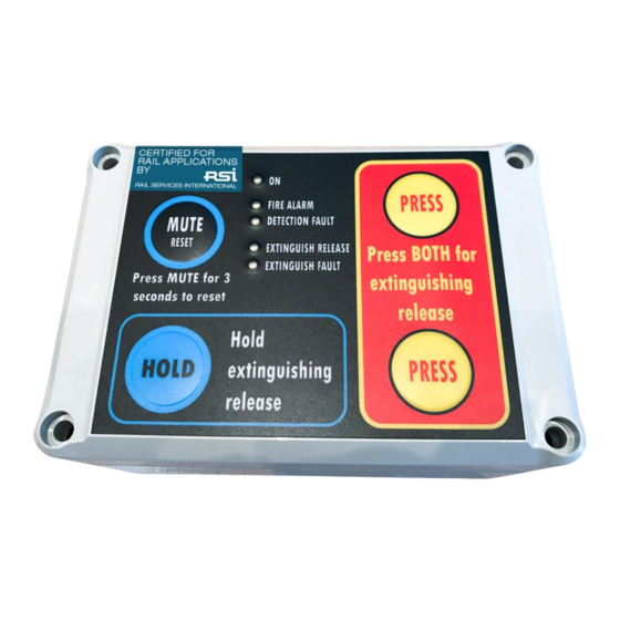
3. SFCP Rail Controls and Indications The SFCP Rail has a clear front panel display enabling the current state of the SFCP Rail to be rapidly determined. Figure 3.0 shows the controls and indications. Figure 3M SFCP Rail front panel controls and indications 3.1 Controls... -
Page 10: Indications
The fire extinguishing device will be released, depending on the dip-switch (time) settings. If the SFCP Rail is set up in the direct fire mode, pressing both extinguishing release buttons will override the extinguishing delay at start the extinguishing release immediately. - Page 11 The Extinguish Fault LED The yellow Fault (Fire suppression) LED is lit when a fault is detected in the fire-extinguisher line. In normal state (no fire) a monitoring current of <4 mA is supplied to the extinguishers. If R>300 Ohm, the Extinguish Fault is triggered.
-
Page 12: Connections Of The Sfcp Rail
4. Connections of the SFCP Rail The SFCP Rail has the connections on the back of the control panel. It´s components, except the connections and the dip-switches are moulded in plastic for a IP protection. Figura 4.0 shows the controls and indications. - Page 13 The rear of the SFCP Rail will have the following connections: CONNECTOR X4: 1. FAULT Normally-closed connection 2. FAULT Normally-open connection 3. FAULT Common (engaged an any fault condition) 4. FIRE Normally-closed connection 5. FIRE Normally-open connection 6. FIRE Common (indicates upcoming extinguisher activation) 7.
-
Page 14: Dip-Switches Settings
5. Dip-Switches Settings The SFCP Rail can be commissioned in a basic manner by using the settings of the dip-switches. Figure 4.0 shows the location of the dip-switches. 5.1 Direct fire Dip-switch Position up: In the direct fire mode the dual release extinguishing buttons (fire buttons) on the... -
Page 15: Single Or Dual Fire Alarm Dip-Switch
5.4 Single or Dual Fire Alarm Dip-switch Position up: In single mode the extinguisher(s) will be released when one of the zones will have a fire alarm condition. Position down: In dual mode the extinguisher(s) will be released after both zones will have a fire alarm condition. -
Page 16: Sfcp Rail Technical Specification
6. SFCP Rail Technical Specification Power Supply Specification Rated Voltage 11 to 32 Volt DC This means that if the system normally uses a 12VDC input, the battery should Battery Voltage also supply 12VDC input, or if the normal voltage is 24VDC, the battery should also supply 24VDC. - Page 17 General System Spezification Ambient Temperature Range -40 to 70 degrees Celsius Environment Waterproof IP68 Dimensions See figure below. Version 03 – 30.10.2019 Seite 17 von 20...
-
Page 18: Appendix 1 Sfcp Rail Wiring Diagram
Appendix 1 SFCP Rail Wiring Diagram The diagram below shows the SFCP Rail connections and dip-switches Version 03 – 30.10.2019 Seite 18 von 20... - Page 19 Version 03 – 30.10.2019 Seite 19 von 20...
-
Page 20: Appendix 2 Devices Supported By The Sfcp Rail
Fire Alarm Sounder RoLP 32 red Cooperfulleon Fire Alarm Sounder Beacon combined RoLP LX Wall Cooperfulleon Flashing Sounder PA X 1-05 Pfannenberg Always check the specification of the devices before installing them on the SFCP Rail. Version 03 – 30.10.2019 Seite 20 von 20...
Need help?
Do you have a question about the SFCP Rail and is the answer not in the manual?
Questions and answers