
Related Manuals for powertronics PT-3000

Summary of Contents for powertronics PT-3000
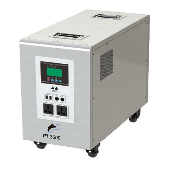
- Page 1 User Manual PT-3000 Powertronics Inc. 370 Mountain St. Willimantic, CT 06226 844-241-1046 www.powertronics.us...
-
Page 2: Dear Customers
Dear Customers: ● Double CPU intelligent control technology. Thank you very much for purchasing Powertronic’s PT-3000. Before use of ● 2 programmable working modes, Grid power & battery power. this product, please read the user manual fully. Please feel free to ●... - Page 3 3.2 Side Panel Icons 3 Unit Diagram/Operation Instructions 3.1 Front panel icons Guide ④ -- AC Input Socket (AC charger) ⑤ -- Cooling Fan Guide ① ⑥ -- 5VDC Output (USB sockets) -- Solar Input Breaker ② ⑦ -- AC Outlets -- Battery Input Breaker ③...
- Page 5 3.3.3 LED Status Description 3.3 Front Panel Instructions LED display Description 3.3.1 LCD display and operation interface, displays the working status of the equipment, including Input/output voltage, frequency, main mode, inverter Light PV start charging Green mode, battery capacity, charge current, total charge load capacity and PV stop charging warnings.
- Page 6 3.3.4.2 Main Menu: From the main screen, press and hold Function 3.3.4 LCD Display Instruction key for 5 seconds to enter the main menu, press DOWN or UP to 3.3.4.1 View the main screen:press DOWN or UP to scroll through the view the sub-menu.
- Page 7 3.3.5 Parameters Setting 3.3.5.1 Buzzer Settings Under the main screen, Press and hold the Function button for 5 seconds to enter the main menu, press the DOWN button to select the buzzer information P4, press the Function button to enter the setting interface, turn on/off the buzzer state through DOWN or UP key, and press the Function key to save and exit.
- Page 8 3.3.5.3 Inverter Working Mode Settings Under the main screen, press and hold the Function key for 5 seconds or less to enter the main menu, press the DOWN key to select the inverter work mode information P1, press the Function key to enter the setting interface, adjust the inverter work mode (01-03) through DOWN or UP key, press the Function key to save and exit.
- Page 9 4.4 Instructions for Connecting Expansion Battery 4.2 System working diagram The external battery’s voltage must be consistent with the unit’s internal battery voltage: 51.2V. Make sure the positive (+) and negative (-) terminals are wired correctly. Reversing polarity may damage the unit. 4.3 Instructions for Solar Power Input Use the correct size of PV cable, make sure the solar power voltage and ⑪...
-
Page 10: Very Important Note
When you want to use the unit as an uninterrupted backup power to your ⑧ When you want to use wall power to charge the unit, Turn on “ -AC input loads, you are suggested to wire the AC input with terminals. Use the correct ④... - Page 11 4.6.2 DC outputs 4.6 Outputs The 5VDC loads are connected to the “①- 5VDC Output”(USB souckets) 4.6.1 AC outputs on the front panel. The total 5VDC USB output current is 2A. ②/⑬-- The AC loads are connected to the “ AC Output”...
-
Page 12: Power On/Run
5.3 Shutdown 5 Power ON/RUN Shutdown: Turn off the loads, disconnect the mains input, and then press the Note: Check and make sure the voltage and polarity of battery and "power on / off button" for 2 seconds, release after the internal relay action, solar panels are connected correctly. -
Page 13: Maintenance
6 Maintenance 5.5 Audio alarm reminder instruction 6.1 This series of product requires little maintenance, battery only needs Buzzing Buzzer is no tweet under default to maintain its charge for full life expectancy. prohibit status. Equipment 6.2 If you do not use the equipment for a long period of time, it is Buzzer tweet 4 times every 15s, running normal Buzzer... -
Page 14: Technical Data Sheet
8 Technical Data Sheet 7 Simple Fault Diagnosis and Trouble Shooting WARNING: There is high voltage inside the machine! Do not open and Model try to repair or maintenance, high voltage may cause shock or death! Battery rated voltage(vdc) 51.2 Failure Possible reason solution...
Need help?
Do you have a question about the PT-3000 and is the answer not in the manual?
Questions and answers