Table of Contents
Advertisement
Quick Links
4 BBL TBI SYSTEMS
550-400 (700 CFM – 65 lb/hr injectors) up to 400 HP
550-401 (900 CFM – 75 lb/hr injectors) up to 525 HP
550-402 (900 CFM – 85 lb/hr injectors) up to 600 HP
INSTALLATION MANUAL – 199R10552
NOTE: These instructions must be read and fully understood before beginning installation. If this manual is not fully
understood, installation should not be attempted. Failure to follow these instructions, including the pictures
may result in subsequent system failure.
NOTE: Fits all standard square flange intake manifolds.
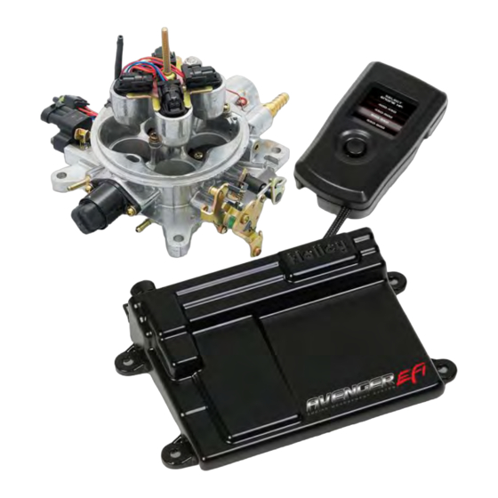
AVENGER EFI
TBI HARDWARE
1
Advertisement
Table of Contents

Related Manuals for Avenger 550-400

Summary of Contents for Avenger 550-400
- Page 1 AVENGER EFI 4 BBL TBI SYSTEMS 550-400 (700 CFM – 65 lb/hr injectors) up to 400 HP 550-401 (900 CFM – 75 lb/hr injectors) up to 525 HP 550-402 (900 CFM – 85 lb/hr injectors) up to 600 HP TBI HARDWARE INSTALLATION MANUAL –...
-
Page 2: Table Of Contents
6.0 TOOLS REQUIRED FOR INSTALLATION ..........................7 7.0 COOLANT TEMPERATURE SENSOR INSTALLATION ......................7 8.0 REMOVAL OF EXISTING FUEL SYSTEM ..........................7 9.0 AVENGER EFI TBI SYSTEM INSTALLATION ........................8 9.1 Throttle Body..................................8 9.2 Throttle Connections ................................8 9.3 MAP Sensor Installation and Vacuum Line Connections..................... 9 9.4 Fuel Pump, Fuel Line, and Filter Installation ........................ -
Page 3: Introduction
This information should be found on the RTV package. 2.0 CHOOSING THE RIGHT SYSTEM: To ensure that you have purchased the correct AVENGER EFI kit for your application, check to be sure that the kit you purchased is listed beside your engine’s horsepower. HORSEPOWER KIT PART NUMBER Up to 400 hp ........550-400 AVENGER EFI TBI, 700 CFM 65 lb/hr injectors... -
Page 4: Warnings, Notes, And Notices
TBI Assembly 700 CFM 65 lb/hr Complete 534-172 TBI Assembly 900 CFM 75 lb/hr Complete 534-187 TBI Assembly 900 CFM 85 lb/hr Complete 534-173 Avenger EFI ECU and Handheld 554-116 Main Power Harness 558-308 Avenger EFI TBI Wiring Harness 558-100... - Page 5 Item 1 Item 2 Item 3 Item 4 Item 5 Item 6 Item 7 Item 8 Item 9 Item 10 Item 11 Item 12 Item 13 Item 14 Item 15...
- Page 6 Item 16 Item 17 Item 18 Item 19 (Pre-Installed in Harness) Item 20 Item 21 Item 22 Item 23 Item 24 Item 25 Item 26 Item 27 Item 28 Item 29 Item 30 Item 31 Item 32 Item 33 Item 34 Item 35...
-
Page 7: Additional Items Required For Installation
A 0-30 psi fuel gauge and tee fitting for fuel gauge is recommended to check for proper fuel pressure. PN 554-102 is a 0-100 PSI pressure sensor that can be purchased as well that will plug into the Avenger harness to check and monitor fuel pressure. -
Page 8: Avenger Efi Tbi System Installation
Remove the shop towels from the intake and vacuum out the intake channel to ensure no dirt or debris is left in the intake system. Place a shop towel over the entire intake opening until you are ready to install the new AVENGER EFI TBI. -
Page 9: Map Sensor Installation And Vacuum Line Connections
The following section covers the installation of an in-line pump. Holley in-line fuel pump PN 12-920 is included with this kit. Holley includes both a pre and post filter with the AVENGER TBI system. Both of these filters have “barbed” ends and are designed to connect to an EFI pressure rated rubber hose. - Page 10 Mount the electric fuel pump as close to the fuel tank outlet as possible with the bracket provided. Mounting the fuel pump in this manner will insure that the pump will prime easily and purge fuel vapors in the TBI quickly to ensure faster starts. DANGER! Take precautions to ensure that all fuel line routings are away from heat sources, such as the engine or exhaust pipes.
-
Page 11: Return Line Installation
9.5 Return Line Installation The Holley AVENGER EFI TBI system requires a return fuel line to the fuel tank. Some late model vehicles that were originally equipped with a throttle body injection system may already have a return line to the fuel tank that can be utilized. If a return fuel line must be installed, a minimum size of 5/16”... -
Page 12: Oxygen Sensor Installation
If you have long tube headers, mount the sensor approximately 1-10” after the collector or in the header collector itself. Avenger EFI systems come with a Bosch wideband oxygen sensor. Make sure your sensor looks like Figure 6. Figure 6 9.6.1 Oxygen Sensor Mounting Procedure... -
Page 13: Ecu Mounting
11.1 Main Power/Battery Connection The AVENGER ECU has a main battery power and ground connector on the right side of the ECU. The bottom position, Terminal “A” is the ground. The upper position, Terminal “B” is the positive terminal. Always use the fused power cable with the proper connectors supplied by Holley only. -
Page 14: Primary Harness Installation And Sensors Connection
ECU. Figure 9 12.1 ECU Connectors AVENGER ECU – The AVENGER ECU has two main connectors: P1A - The first connector next to the USB connector is the “P1A” connector (34 pin). This connector is primarily an “Input”... -
Page 15: Throttle Position Sensor (Tps)
Connect to the oxygen sensor connector to the oxygen sensor previously installed. If you need an extension cable, one is available from Holley (P/N 534-199). The Avenger systems are intended to be used with a Bosch wide band oxygen sensor supplied by Holley. -
Page 16: Fuel Pressure (Fuel)
The white wire should be connected to a +12 volt source switched ignition source. The handheld does not have to be powered/installed after the vehicle is up set up and running properly. Figure 18 Harness to Handheld Figure 19 Handheld 12.3.10 Knock Sensor (Knock) The knock sensor connector is NOT used on Avenger systems. Figure 20 Knock... -
Page 17: Ignition (Ign)
12.3.11 Ignition (IGN) There is a 10 pin connector marked “IGN”. This is to connect to various ignition systems. This is not required for some applications. See section 16.0 below for proper ignition wiring. Figure 21 IGN 13.0 PRIMARY OUTPUTS 13.1 Idle Air Control (IAC) Connect to the idle air control motor which is installed in the throttle body. -
Page 18: Ignition/Engine Speed Input
Figure 25 Points Output – Color = White – This wire is NOT used with the Avenger system. Tape up the end or install heat shrink in it. Chassis Ground – Color = Black – Connect to a chassis ground point that has excellent connectivity with both the engine and the battery. -
Page 19: Wiring
NOTE: Using this input, the EFI will NOT control the ignition timing of the engine. The timing will be based on the distributor initial, mechanical, and vacuum advance, just like it did with a carburetor. OPTION 3) “GM Small Cap HEI” Computer Controlled Distributor – ... - Page 20 Figure 28 below shows how to connect to a factory style ignition with a canister style coil. Figure 28 OPTION 2 – “Tach Out’ – If using an aftermarket Capacitive Discharge (CD) ignition system, you need to connect to the “Tachometer Output”...
- Page 21 OPTION 3 - “GM Small Cap HEI” Computer Controlled Distributor – An ignition adapter to connect to a computer controlled small cap HEI distributor is included with all Small and Big Block Chevy multi-port Avenger EFI kits. This adapter looks like: Figure 31 Connect this adapter to the main EFI harness to the connector marked “IGN”...
-
Page 22: Additional Outputs
Figure 33 17.0 ADDITIONAL OUTPUTS There are 3 optional outputs available on the system that can be use for the following features: Air Conditioning Shutdown at wide open throttle Electric Fan #1 output Electric Fan #2 output There outputs are located in the “Input/Output”... -
Page 23: Appendix 1.0
APPENDIX 1.0 Pinout The following shows pins that are used on Avenger systems. Pins that are not used on Avenger systems, but may have wires populated in the harness, are denoted with an asterisk (*). Connector P1B Connector Function Function Coil –... - Page 24 Holley Performance Products 1801 Russellville Road Bowling Green, KY 42101 Technical Service: 1-270-781-9741 Fax: 1-270-781-9772 For online help, please refer to the Technical Information section of our website: www.holley.com 199R10552 wf Date: 5-10-11...
- Page 26 199R10552 wf Date: 5-10-11...
Need help?
Do you have a question about the 550-400 and is the answer not in the manual?
Questions and answers