Table of Contents
Advertisement
Quick Links
Advertisement
Chapters
Table of Contents

Summary of Contents for Japan Radio Co. NKG-84
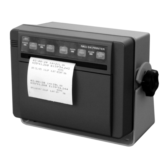
- Page 1 NKG-84 PRINTER プリンタ INSTRUCTION MANUAL 取扱説明書...
- Page 3 ● ● PREFACE ● ● Thank you for purchasing the NKG-84 JRC Printer. The JRC Printer automatically receives and prints out data from a navigator. ●Before using the printer, carefully read this INSTRUCTION MANUAL so as to fully understand the proper usage and handling.
-
Page 4: Before Operation
● ● Before Operation ● ● Alert Symbols A number of alert symbols are used in this manual and labeled on the product itself to ensure safe and proper usage, and to prevent possible injury to you or others and to avoid possible property damage during operation or maintenance. -
Page 5: Operating Precautions
● ● Operating Precautions ● ● WARNING Do not place heavy objects on the printer. Failure to observe this warning could result in the unit becoming unbalanced and thus causing injury if it falls. Do not put a heavy thing on the power and data cables. Fire, electrical shock, and failure can be caused. - Page 6 ● ● Operating Precautions ● ● CAUTION Do not place the printer on an unstable surface. If placed on an unstable table or an uneven surface, it could fall and result in personal injury and/or damage or malfunction of the unit. Fix the printer steadily using the supplied screws.
-
Page 7: After Unpacking
AFTER UNPACKING After unpacking, make sure that the following components and accessories are all present. If any components or accessories are missing, please contact your dealer or the nearest JRC sales. NKG-84 Printer Component Model/Part Number Quantity Printer NKG-84 Mounting screws... -
Page 8: Equipment Appearance
EQUIPMENT APPEARANCE... -
Page 9: Table Of Contents
Contens PREFACE............................i Before Operation ..........................ii OPERATING PRECAUTIONS ......................iii After unpacking ..........................v AFTER INSTALLATION........................v EQUIPMENT APPEARANCE ......................vi Chapter 1 Equipment Overview ............1 1.1 Functions ........................1 1.2 Features .......................... 1 1.3 Configuration ........................2 1.4 Structure .......................... - Page 10 Chapter 5 Maintenance and Inspection ..........26 5.1 Maintenance ......................... 26 5.1.1 Daily check ......................26 5.1.2 Periodic check ....................26 5.1.3 Other general maintenance and check items ............ 27 5.2 If Paper Becoms Jammed .................... 28 5.3 Fuse Replacement ....................... 28 5.3.1 Removing casing ....................
-
Page 11: Chapter 1 Equipment Overview
Chapter 1 Equipment Overview 1.1 Functions This equipment is intended to receive navigation data such as the location, time, speed and course sent from a DGPS/GPS navigator or other equipment. It also can print water temperature, depth and tidal current data together with the navigation data by connecting the Japan Radio navigation interface. -
Page 12: Configuration
This equipment can be operated with DC power. To use AC power, an optional power unit (NBA-4534A or NBG- 122) is available. This equipment is connected with a navigator or navigation interface to print data. Navigator NKG-84 printer NDF-167 DC10.8〜35V Navigation interface... -
Page 13: Structure
1.4 STtructure (Unit: mm) NKG-84 Printer... -
Page 14: Schematic Diagram
1.5 Schematic Diagram Overall system diagram of the NKG-84 printer and receiver... -
Page 15: Chapter 2 Names And Functions Of Components
Chapter 2 Names and Functions of Components 2.1 Front Panel View of equipment with printer paper storage cover opened: POWER lamp Pressing the POWER switch activates the green POWER lamp to indicate that the power has been turned on. POWER switch Turns the printer on and off. - Page 16 PAPER lamp This orange lamp blinks to indicate that the equipment has run short of printer paper. FEED switch Pressing this switch feeds printer paper from the printer. Paper is fed, line by line, with each press of the switch. Pressing and holding it down feeds the paper continuously.
-
Page 17: Rear Panel
2.2 Rear Panel View of the equipment with rear cover removed: Data input terminal (A/B) Inputs data from a navigator. Grounding terminal (EARTH) This terminal is for electrical grounding to the vessel. Power terminal (DC+/DC-) Connect the power supply to these terminals. The voltage range of the power supply is from 10.8 to 35.0 VDC. -
Page 18: Chapter 3 Installation
Chapter 3 Installation WARNING Never carry out the receiver installation by a user. Ask your nearest branch, business office or a dealer for inspection and repair. 3.1 Fastening the Receiver 3.1.1 Site selection The receiver is designed so that be installed on either a desk, a wall, or the ceiling of the vessel. Select an installation location that satisfies the criteria listed on the following page. - Page 19 Criteria for site selection (a) The distance from the magnetic compass should be at least 1 meter. (b) The length of the grounding wire should be minimized. (c) The installation location should be as free as possible from direct sunlight. (d) The insallation location should also be: free from excessive heat moisture, and vibration;...
-
Page 20: Installation Procedure
3.1.2 installation procedure The following are the procedures for installing the printer: (1) Loosen the knobs of the printer and remove it from the mounting base. (2) Screw down the mounting base at the desired location. (3) Remount the printer onto the mounting base and then tighten the knobs to lock the printer in place. Fig. -
Page 21: Equipment Component Connection
Depending on whether the built-in or optional power unit is to be used, connect the equipment components correctly as shown in one of the following figures. 3.2.1 When the power unit is to be used NKG-84 Printer Navigator INPUT POWER [DC10.8-35V] 12 (-). - Page 22 Fig. 3-3-2 Wiring to the rear terminal block when the power unit is used...
-
Page 23: When Inboard Dc Power Is Used
3.2.2 when the inboard DC power is used NKG-84 printer Navigator INPUT POWER [DC10.8-35V] (E) 10 12 (-) (+) 11 * NDF-167 * Navigation interface DC12/24V Fig. 3-4-1 Interconnections when the inboard DC power is used... - Page 24 Hull ground DC power Navigator Fig. 3-4-2 Wiring to the rear terminal block when the inboard power unit is used...
-
Page 25: Cable Connection
3.3 Cable Connection Remove the cover from the rear bottom of the printer, and connect, power cable, and all other necessary cables to the terminal board. All cables can be connected using a screwdriver. 3.3.1 Connecting the cable Connect the antenna cable to the appropriate antenna terminal on the terminal board. CAUTION When connecting the data cable to the terminal block, do not wire cable conductors in reverse with the instructed connections. -
Page 26: Connection The Power Cable
3.3.2 Connecting the power cable Connect the power cable to the power terminals on the terminal board. WARNING Do not operate at voltages other than 10.8 - 35.0 VDC. Failure to observe this warning could result in fire, electrical shock, and/or malfunction. CAUTION Do not reverse the polarity of the power supply connection. -
Page 27: Chapter 4 Printer Operations
Chapter 4 Printer Operations 4.1 Turning Power On Press and hod the POWER switch for at least two seconds. POWER ▼ The green POWER lamp will turns on. 4.2 Loading Printer Paper Proceed as follows to set printer paper: (1) Cut the leading edge of the paper straight across. CAUTION Cut the leading edge of the paper straight. - Page 28 (2) Set the printer paper into the printer. Open the paper cover and pull out the paper shaft. Insert the shaft into the center of the roll of paper. ▼ Manually feed the paper through the slot until the edge of the paper reaches the mouth. ▼...
-
Page 29: Feeding The Printer Paper
(3) Insert the paper into the paper holder. When the leading edge of the paper comes out through the printer. ▼ Set the paper shaft in the holder with paper. 4.3 Feeding The Printer Paper Press the FEED switch. FEED ▼... -
Page 30: Printing Received Data
4.4 Printing Received Data ● Status of the equipment for data reception Illuminated: Indicates that data is being received. Illuminated: This is illuminated when data is interrupted. ● Printing The equipment prints data automatically at the preset print intervals. The print interval is OFF, 1 min, 3 min, 5 min. 10 min, 20 min, 30 min or 60 min. Press [▲] switch to increase the print interval. - Page 31 Print Sample ● In case of connecting to the Navigator Local time (In case U is appeared, time is UTC) Year, month, day Time Fixed mode Satellite number in use Geodetic System* Current Position Bearing to destination from current positiion DOP level (Magnetic bearing) Antenna height...
- Page 32 Printing items vs data in use...
-
Page 33: Stop The Alarm
4.5 Stopping the Alarm If the printer paper runs short. If the printer paper runs short, an alarm buzzer will sound and the alarm lamp will blink. ▼ Press the ALARM OFF switch. ALARM OFF ▼ The alarm buzzer will stop sounding. The alarm lamp will continue blinking. Supply the printer with paper. -
Page 34: Self-Diagnostics
4.8 Self-Diagnostics Press the [TEST] switch to start self-diagnostics. TEST Contents of the self-diagnostics ¡ POWER, RECEIVE, PAPER and ALARM LEDs will flash. ¡ The segment LEDs of the display will flash as follows. H → I → O → X ¡... -
Page 35: Rom Testing
4.9 ROM Testing Press the [ROM] switch to perform ROM testing. If there is no error in the ROM. O and K will be shown alternately on the display. If there is an error in the ROM, N and G will be shown alternately on the display. 4.10 RAM Testing Press the [RAM] switch to perform RAM testing. -
Page 36: Chapter 5 Maintenance And Inspection
Chapter 5 Maintenance and Inspection 5.1 Maintenance To maintain the equipment always in its best condition, it is important to perform maintenance checks and record the results. Thus, potential problems can be detected early and trouble can be avoided. 5.1.1 Daily check Without printer paper, you cannot obtain necessary information. -
Page 37: Other General Maintenance And Check Items
5.1.3 Other general maintenance and check items In addition to periodic checks by the self-diagnostic tests, it is recommended to check the following periodically. CAUTION When loading the printer paper, cut the leading edge straight. Uneven cutting may cause the paper to jam. Note: If the “out of paper”... -
Page 38: If Paper Becoms Jammed
5.2 If Paper Becomes Jammed If the paper jams near the printer head, ask your nearest branch, business office or a dealer for inspection and repair. CAUTION If the paper in the printer jams, do not continue pressing the FEED switch. When loading paper into the printer, cut the leading edge straight. - Page 39 Fig. 5-3 Removing the casing...
-
Page 40: Replacing Fuses
5.3.2 Replacing fuses WARNING The power switch on the power distribution panel must be turned off during replacing a fuse. When replacing a fuse, use extreme caution not to bring it into contact with adjacent ones. Short-circuiting due to making contact may cause power and/or circuit board damage. -
Page 41: Maintenance Component Lists
5.4 Maintenance Component Lists 5.4.1 Maintenance parts Parts for the NKG-84 printer Part name Model number JRC part code Fuse MF51NN-3.15A 5ZFAD00227 Printer paper H-7ZPJD0044 7ZPJD0044... -
Page 42: Chapter 6 After-Sales Service
Chapter 6 After-Sales Service ◆ When Requesting Repair (1) If you suspect that a problem has occurred, take the appropriate remedial action after completing the following diagnostic : a) Check the rear terminal board of the equipment for loose or disconnected cables. b) Check that the required voltage is supplied to the power input terminals on the rear terminal board of the equipment. -
Page 43: Chapter 7 Disposai
Chapter 7 Disposal If this product is to be disposed disposed of, process it in accordance with the legal regulations of the local government having jurisdiction. For further details, please contact your dealer or JRC sales/service representative or the local government having jurisdiction. Materials ..See mechanical parts list of appendix 1 at the appendix of this manual. -
Page 44: Chapter 8 Specifications
Chapter 8 Specifications 8.1 Printer Printer scheme Thermosensitive 7 x 5 dot matrix Total characters / line Printer paper 7ZPJD0044, 80mm x 60mm across x 40 m Out-of paper warning Alarm buzzer Operating panel lamp blinking Red end-of-paper line markers on printer paper (the red lines indicate there is one meter or less remaining) 8.2 Control Power on / off... -
Page 45: Mechanical Specifications
8.6 Mechanical Specifications Minimum and maximum temperature Operating -15 to +55˚C Storage -25 to +70˚C Relative humidity Up to 95% at 40˚C Dimensions 246mm wide x 170mm high x 133mm deep (With mounting base) Installation Wall-mounting, desk-mounting, or ceiling-mounting Mass 2.0 kg (with mounting base) -
Page 46: Appendix
Appendix 1. Mechanical Details Fig. AP-1 Machine construction drawing of the NKG-84 printer (1) - Page 47 Fig. AP-1 Machine construction drawing of the NKG-84 printer (2)
-
Page 48: Mechanical Parts List
2. Mechanical Patrs List Description JRC Part code Q’ty Material Bezel Aseembly MPBC33719 Consisting of : Front Bezel MTV302423 Packing Rubber MTT023560 Paper Cover MTV302424 Cabinet MTV000310C Mounting Base MTV000313B Gasket MTT023562 Center Shaft MTH004065 Aluminum Receiver PCB CMN-2330 Shield Cover MTB159034 Iron Main Processor Assembly... -
Page 49: List Of Geodetic Systems
3. List of Geodetic Systems Geodetic systems WGS-84 WGS-72 Japanese geodetic system North American 1927 (USA) North American 1927 (Canada and Alaska) Europe 1950 (Europe) Australia geodetic 1966 (Australia) Ordance Survey of Great Britian (UK) NAD-83 Adindan (Ethiopia and Sudan) ARC 1950 (Botswana) Australiam Geodetic 1984 (Australia) Bermuda 1957 (Bermuda island) - Page 51 NKG-84 プリンタ 取扱説明書...
- Page 53 <はじめに> このたびは、プリンタ NKG-84 をお買い上げいただきまして、誠にありがとう ございます。 本装置は、航法装置のデータを自動的に受信して印字する機能を持っています。 ● お使いになる前に、この取扱説明書をよくお読みのうえ、正しくお使いくだ さい。 ● 取扱説明書は必要なときに参照できるよう大切に保管してください。 ● 万一、ご使用中にわからないことや不具合が生じたときにお役立てください。...
- Page 54 <ご使用のまえに> 絵表示について この取扱説明書および製品への表示では、製品を安全に正しくお使い いただき、あなたや他の人々への危害や財産への損害を未然に防止す るために、いろいろな絵表示をしています。その表示と意味は次のよ うになっています。内容をよく理解してから本文をお読みください。 この表示を無視して誤った取扱いをすると、人が死亡または重傷を 警告 負う可能性が想定される内容を示しています。 この表示を無視して誤った取扱いをすると、人が傷害を追う可能性 注意 が想定される内容および物的損害のみの発生が想定される内容を示 しています。 絵表示の例 △記号は注意(危険・警告を含む)が必要な内容があることを告げる ものです。 図の中に具体的な注意内容(左図の場合は特定しない一般的な注意) が描かれています。 記号は禁止の行為であることを告げるものです。図の中や近くに 具体的な禁止内容(左図の場合は分解禁止)が描かれています。 ●記号は行為を強制したり指示する内容を告げるものです。図の中に 具体的な指示内容(左図の場合は電源プラグをコンセントから抜け) が描かれています。...
- Page 55 <ご使用上の注意> 警告 装置の上に重いものを置かないでください。バランスがくずれて倒れたり、落下した りして、けがの原因となります。 電源ケーブルやデータケーブルの上に重いものを乗せないでください。火災、感電、 故障の原因となります。 装置の入力電圧には、直流 10.8V 〜 35V 以外の電源で使用しないでください。火災、 感電、機器の故障の原因となります。 万一、煙がでている、変な臭いがするなどの異常に気がついたときは、すぐに電源ス イッチを切り、その後必ず分電盤の電源スイッチを切ってください。煙が出なくなる のを確認してから、お買いあげの販売店またはお近くの当社の支社、支店、営業所に 修理をご依頼ください。そのまま使用すると火災、感電の原因となります。...
- Page 56 <ご使用上の注意> 注意 ぐらついた台の上や傾いた所など不安定な場所に設置しないでください。落ちたり、 倒れたりしてけがの原因となることがあります。 設置には、付属のねじを用いてしっかりと固定してください。 露出甲板や水揚など、水分や湿気の多い場所では使用しないでください。感電や故障 の原因となることがあります。 装置を開けないでください。内部をさわると感電の原因となることがあります。保守 等でやむを得ず内部を点検する場合は、必ず装置に給電している分電盤の電源スイッ チを切ってから点検してください。 直射日光や暖房により直射熱を受ける場所や、湿気やほこりの多い場所に設置しない でください。火災、故障、プリンタの印字不明瞭の原因となることがあります。 プリンタ用紙は、弊社推奨以外のものを使用しないでください。プリンタの故障や印 字の不明瞭の原因となることがあります。 お手入れの際には、ベンジン、アルコール、シンナーなどは使わないでください。塗 装がはげたり、変質する原因となることがあります。 お手入れは、柔らかい布で軽く拭き取ってください。...
- Page 57 ご確認のお願い 開梱いたしましたら、下記の品物がすべて入っていることをご確認してください。もし、不足の物 品がございましたら、お買い上げの店、または最寄りの当社営業所にご連絡をお願いいたします。 NKG-84 プリンタ 品 名 型 名 数 量 プリンタ NKG-84 取付ネジ MPTG02024A プリンタ用紙 H-7ZPJD0044 取扱説明書(和/英文) 7ZPNA0721 予備品(ヒューズ) H-6ZXAF00021 装備記録票 H-7ZPJD0065 装備記録票のご返送のお願い 機器の据え付けが終了しましたら、同封の装備記録票を下記まで FAX にてご返送ください。 宛先:〒 141-0032 東京都品川区大崎 1-18-7 日本無線株式会社 マリンサービス部 FAX No. 03-3779-1420...
- Page 58 機器外観...
- Page 59 目 次 はじめに ……………………………………………………………………………………… 43 ご使用の前に ………………………………………………………………………………… 44 ご使用上の注意 ……………………………………………………………………………… 46 ご確認のお願い ……………………………………………………………………………… 47 装備記録表のご返送のお願い ……………………………………………………………… 47 機器外観 ……………………………………………………………………………………… 48 第 1 章 装置のあらまし ………………………………… 51 1.1 機 能 ……………………………………………………………………… 51 1.2 特 長 ……………………………………………………………………… 51 1.3 構 成 ……………………………………………………………………… 51 1.4 構 造 ……………………………………………………………………… 52 1.5 総合系統図 ...
- Page 60 4.9 ROM テスト ……………………………………………………………… 73 4.10 RAM テスト ……………………………………………………………… 73 4.11 印字 和文/英文切替 …………………………………………………… 73 第 5 章 保守・点検 ……………………………………… 74 5.1 保守点検 …………………………………………………………………… 74 5.1.1 日常点検 ……………………………………………………………… 74 5.1.2 定期点検 ……………………………………………………………… 74 5.1.3 その他の一般的な保守点検 ………………………………………… 75 5.2 紙詰まりになったときの処置 …………………………………………… 76 5.3 ヒューズの交換方法 ……………………………………………………… 76 5.3.1 ケースの取り外し ...
-
Page 61: 第 1 章 装置のあらまし
第 1 章 装置のあらまし 1.1 機 能 本装置は DGPS / GPS 航法装置等から送信される、位置、時刻、速度、進路等の航法データを受 信し、印字するものです。又日本無線(株)製、航法インターフェースを接続することにより、航 法データと一緒に水温、水深、潮流データを印字できます。 1.2 特 長 ○航法データの印字 指定した印字間隔で自動的に航法データを印字します。 又随時手動で航法データを印字できます。 ○和文/英文印字 和文又は英文をメニューで切り替えて印字できます。 ○広い電源電圧範囲 直流 24 ボルト船のほか、直流 12 ボルト船にもそのまま使えます。 ○自己診断機能 自己診断機能を備えていますので、保守点検が容易です。 1.3 構 成 本装置は直流電源で使用できます。交流電源使用の場合には、オプションの電源ユニット(NBA- 4534A あるいは NBG-122)で使用できます。 航法装置あるいは航法インターフェースと接続してデータを印字します。 航法装置 NKG-84 プリンタ NDF-167 DC10.8〜35V 航法インタフェース NBG-122/NBG-4534A 電源ユニット (AC100-120V/220-240V) -
Page 62: 構 造
1.4 構 造 (単位: mm) NKG-84 プリンタ 外形図... -
Page 63: 総合系統図
1.5 総合系統図 NKG-84 プリンタ 総合系統図... -
Page 64: 第 2 章 各部の名称とはたらき
第 2 章 各部の名称とはたらき 2.1 前 面 紙収納カバーを開けたときの図です。 1 :[POWER]表示 POWER スイッチを押して電源を入れると、緑色のランプが点灯します。 2 :[POWER]スイッチ 受信機の電源を入/切をするスイッチです。 3 :[RECEIVE]表示 信号を検出すると点灯し、データを受信中に点滅します。 4 :[PRINT]スイッチ スイッチを押すと、随時印字ができます。 5 :[DIMMER]スイッチ ランプの明るさを調節するスイッチです。 スイッチを押すごとに、明るさが切り替わります。 なお、 [PAPER] [ALARM]ランプの明るさは変わりません。 6 :[PAPER]表示 プリンタ用紙がなくなったときに、橙色のランプが点滅します。 7 :[FEED]スイッチ... - Page 65 プリンタ用紙をプリンタから送り出すスイッチです。 スイッチを押すごとに、1 行ずつ送り出します。また、押し続けると連続して送り 出します。 8 :[ALARM]表示 重要電文を受信したときに、赤色のランプが点滅します。 9 :[ALARM OFF]スイッチ 重要電文を受信したとき、あるいは紙切れになったときに警報を止めるスイッチで す。 10 :[J/E]スイッチ 印字の和文/英文を切りかえるスイッチです。 11 :[ROM] ROM テストを行うスイッチです。 12 :[RAM] RAM テストを行うスイッチです。 13 :[TEST] 自己診断テストを行うスイッチです。 14 :[▲]スイッチ スイッチを押すごとに印字間隔が増えます。 15 :[▼]スイッチ スイッチを押すごとに印字間隔が減ります。 16 :表示器 印字間隔、和文/英文印字、ROM テスト結果、RAM テスト結果を表示します。 17 :プリンタ用紙 データを印字させるための用紙です。用紙が残り少なくなると、用紙の両端に赤い 線が表示されます。 18 :プリンタ...
-
Page 66: 背 面
2.2 背 面 背面カバーをはずしたときの図です 1 :データインプット端子(A / B) 航法装置からのデータを入力します。 2 :アース端子(EARTH) 船体アース用の端子です。 3 :電源端子(DC +/ DC −) 電源を接続します。 入力できる電源電圧範囲は、直流で 10.8V 〜 35V です。 4 :ヒューズ DC(+)および DC(−)ラインに、それぞれ 3.15A の溶断型のヒューズが取り付 けられています。... -
Page 67: 第 3 章 設置方法
第 3 章 設置方法 注意 お客さまによる機器の設置及び移設は、行わないでください。 機器の設置及び移設は、販売店にご依頼ください。 機器の設置・移設及び追加設置を行うときには販売店と御相談ください。 3.1 プリンタの固定 3.1.1 据え付け場所の選定 本受信機は、卓上、壁、天井に据え付けることができます。据え付け場所は、次ページの基準から 選定してください。 警告 ぐらついた台の上や傾いた所など、不安定な場所に設置しないでください。落ちたり 倒れたりして、けがの原因となります。 装置の上に重いものを置かないでください。バランスが崩れて、倒れたり落下したり して、けがの原因となります。 電源ケーブルやデータケーブルの上に、重い物を乗せないでください。感電、故障の 原因となります。 露出甲板や水場など、水分や湿気の多い場所に設置しないでください。感電や故障の 原因となります。 注意 直射日光や暖房による直射熱を受ける場所や、湿気やほこりの多い場所に設置しない でください。火災・故障・プリンタの印字不明瞭の原因となることがあります。... - Page 68 1) マグネットコンパスから 1m 以上離れた場所。 2) 最短距離でアースがとれる場所。 3) なるべく直射日光が当たらない場所。 4) 高温、多湿、過度の振動から避けられる場所。天井に据え付ける場合は熱がこ もらない場所。また、窓際に据え付ける場合は塩水がかからない場所。 5) 下図に示すようなクリアランスが確保できる場所。 なお、接続されるデータケーブル、電源ケーブル、アース線は、送信機、レーダ等 の雑音源やそれらのケーブルから離れた場所に敷設してください。 (単位: ) inch 図 3-1 :プリンタ据え付けに必要なスペース...
-
Page 69: 設置方法
3.1.2 設置方法 下記の要領で、設置してください。 1) 本体のノブをゆるめて、本体を取付台からはずす。 2) 付属のネジで、取付台を希望の場所へ固定する。 3) 本体を取付台に戻し、ノブを締めて固定する。 図 3-2 :取付寸法... -
Page 70: 機器の装備方法
3.2 機器の装備方法 機器の装備は、電源ユニットの有無に応じて、次の図の通りに行ってください。 3.2.1 電源ユニットを使用している場合 NKG-84 プリンタ 航法装置 INPUT POWER [DC10.8-35V] (E) 10 12 (-). (+) 11 * NBG-4534A 電源ユニット * * AC100/220V NDF-167 AC IN + 航法インタフェース DC12V OUT 100V-240V − * * * 図 3-3-1 :電源ユニット使用時の相互結線図... - Page 71 船体アース 航法装置 図 3-3-2 :電源ユニット使用時の背面端子板の配線方法...
-
Page 72: 船内 Dc 電源を使用している場合
3.2.2 船内 DC 電源を使用している場合 NKG-84 プリンタ 航法装置 INPUT POWER [DC10.8-35V] (E) 10 12 (-) (+) 11 * NDF-167 * 航法インタフェース DC12/24V 図 3-4-1 :船内 DC 電源使用時の相互結線図... - Page 73 船体アース 船内DC電源 航法装置 図 3-4-2 :船内 DC 電源使用時の背面端子板の配線方法...
-
Page 74: ケーブルの接続
3.3 ケーブル接続 本体背面下部のカバーをはずし、端子板へデータケーブル、電源ケーブルを接続してください。プ ラスまたはマイナスいずれかのドライバーで接続できます。 3.3.1 データケーブルの接続 端子板のアンテナ端子に、アンテナからのケーブルを接続します。 注意 データケーブルを端子板に接続する際は、芯線を指示と逆に配線しないでください。 データが受信できなくなります。 ◆推奨ケーブル: がい装付きケーブル → 型名:* 250V-TTYCS-1 相当品 1) 端子板のデータケーブル入力端子のネジを緩めてください。 2) ケーブルをガスケットに通してください。 3) ケーブルの芯線を端子板の左から 6 番目と 7 番目に指示に従って挿入してください。 4) ネジを締めて固定してください。... -
Page 75: 電源ケーブルの接続
3.3.2 電源ケーブルの接続 端子板の電源端子に、電源ケーブルを接続します。 警告 電源電圧は、直流 10.8V 〜 35V 以外の電圧で使用しないでください。火災、感電、故 障の原因となります。 注意 電源の極性を逆にして接続しないでください。機器の故障の原因となることがありま す。 ◆推奨ケーブル: 2 線シールドケーブル → 型名: DPYC-1.5 相当品 1) 端子板電源入力端子の[DC +]と[DC −]のネジを緩めてください。 2) ケーブルをガスケットに通してください。 3) プラス側を[DC +]端子に、マイナス側を[DC −]に挿入してから、ネジを締め て固定してください。... -
Page 76: 第 4 章 航法装置からのデータを印字するための操作方法
第 4 章 航法装置からのデータを印字するための操作方法 4.1 電源の投入 [POWER]スイッチを 2 秒以上押してください。 POWER ▼ POWER の緑ランプが点灯します。 4.2 プリンタ用紙の入れ方 1) 用紙の先端をまっすぐに切ってください。 注意 用紙の先端は必ずまっすぐに切ってください。まっすぐでないと、紙がつまる原因と なることがあります。 用紙が詰まった際は、無理に逆方向に引き抜かないでください。次の用紙挿入の際に、 用紙が入らなくなることがあります。やむを得ず逆方向に引く抜く時は、ゆっくり、 静かに抜いてください... -
Page 77: プリンタ用紙の送り方
2) プリンタ用紙をプリンタに入れます。 ペーパカバーを開けて紙軸に取り出してください。 紙軸をプリンタ用紙の芯棒に差し込んでください。 ▼ 用紙を挿入口に止まるまで差し込んでください。 ▼ FEED 用紙を手で抑えながら、 [FEED]スイッチを押してください。 3) プリンタ用紙を紙受けに納めます。 用紙の先端がプリンタから出てきたら、紙受けにセットしてください。 4.3 プリンタ用紙の送り方 FEED [FEED]スイッチを押してください。 ▼ 一回押すごとに、一行ずつ送られます。 押し続けると、連続して送られます。... -
Page 78: 受信したデータの印字
4.4 受信したデータの印字 ● データ受信時の機器の状態 点灯:データの受信中を表します。 点灯:データが中断すると点灯します。 ● 印字 設定した印字間隔で自動的に印字します。 印字間隔は、断、1分、3分、5分、10 分、20 分、30 分、60 分です。 [▲]スイッチを押しますと、印字間隔が増えます。 ▲ 印字間隔は表示器に下記のように表示されます。 断 1 分 3 分 5 分 10 分 20 分 30 分 60 分 表示器 [▼]スイッチを押しますと、印字間隔が減ります。 ▼ PRINT [PRINT]スイッチを押しますと、印字間隔によらず随時印字が できます。 注:航法データ(目的地位置等)の印字を ON/OFF できます。 ALARM POWER +... - Page 79 印字例 ● 航法装置が接続の場合 ローカルタイム (UTCの場合、U) 年月日 時刻 測位モード 測地系* 自船位置 測位衛星番号 DOPレベル 自船から目的地までの アンテナ高 方位(磁気方位) 自船から目的地 目的地までの到達時間 までの距離 航路備位 目的地 目的地位置 航法データ 前目的地 番号 操舵方向 前目的地位置 番号 対地速度 進路 (磁気方位) * 付録「測地系一覧」を参照ください。 ● 航法インターフェースが接続の場合 時刻 年月日 (ローカルタイム) 自船位置 水温値 水深値 潮流データ 速度 進路 注:受信しているデータ中に該当する項目がない場合、その項目は表示されません。...
- Page 80 印字項目と使用データ...
-
Page 81: 警報の停止
4.5 警報の停止 紙切れ時 紙切れになると、警報音が発生し、PAPER ランプが点滅します。 ▼ ALARM [ALARM OFF]スイッチを押してください。 ▼ 警報音が停止します。PAPER ランプは点滅したままです。 新しいプリンタ用紙を入れてください。 ▼ PAPER ランプの点滅が停止します。 4.6 ランプの明るさの調節 DIMMER [DIMMER]スイッチを押してください。 ▼ ランプの明るさが、このキーを押すごとに、 明→中→暗→消灯 と、切り替わります。消灯時は、POWER、ALARM OFF スイッチのバックランプと POWER ランプは消灯しません。 完全消灯する場合は、 [DIMMER]スイッチを 5 秒以上押してください。ただし、 PAPER、ALARM ランプは消灯しません。完全消灯からランプの明るさの調節をする場 合は、 [DIMMER]スイッチを押してください。 4.7 電源断 POWER [POWER]スイッチを 2 秒以上押してください。 ▼... -
Page 82: 自己診断
4.8 自己診断 TEST [TEST]スイッチを押すと自己診断が始まります。 自己診断の内容 ・ POWER、RECEIVE、PAPER、ALARM LED が点滅します。 ・表示器のセグメント LED が下記の順で点滅します。 H → I → O → X ・下記内容が印字されます。 注: Ver 0.0 はプログラムにより変更される場合があります。... -
Page 83: Rom テスト
4.9 ROM テスト [ROM]スイッチを押しますと、ROM テストが行われます。 ROM に異常のない場合は、表示器で O,K, が交互に表示されます。 ROM に異常のある場合は、表示器で N,G, が交互に表示されます。 4.10 RAM テスト [RAM]スイッチを押しますと、RAM テストが行われます。 RAM に異常のない場合は、表示器で O,K, が交互に表示されます。 RAM に異常のある場合は、表示器で N,G, が交互に表示されます。 4.11 印字 和文/英文切替 [J/E]スイッチを押しますと、和文/英文の切替えができます。... -
Page 84: 第 5 章 保守・点検
第 5 章 保守・点検 5.1 保守点検 常に最良の状態を保つために点検を行い、その結果を記録しておくことが大切です。これにより故 障を早期に発見したり、未然に防ぐことができます。 5.1.1 日常点検 プリンタ用紙が無くなっていては、必要な情報が得ることができません。そこで、日常の点検とし て、次の要領でプリンタ用紙の残量を確認してください。 1) 本体前面のペーパーカバーを開けます。 2) プリンタ用紙の残量を確認します。 用紙の左右端に赤ラインが現れていれば、 新しいプリンタ用紙に交換してください。 (赤ラインは、用紙の終了端の 1m 手前から現れます。 ) 3) プリンタ用紙が十分あれば、またはプリンタ用紙の交換が終われば、ペーパーカバ ーを閉じてください。 5.1.2 定期点検 自己診断機能を利用することにより、 各機能ブロック単位での動作状態を点検することができます。 そこで、定期点検として、自己診断テストを行ってください。 1) 操作手順 「4.8 自己診断」 、 「4.9 ROM テスト」 、 「4.10 RAM テスト」を参照してください。... -
Page 85: その他の一般的な保守点検
5.1.3 その他の一般的な保守点検 自己診断機能だけでは確認できない機能の動作状態を確認するため、定期点検とあわせて下記の表 の様な点検を行うことをお勧めします。 注意 プリンタ用紙を挿入する際には、用紙の先端を必ずまっすぐに切ってください。 まっすぐでないと、紙詰まりの原因となることがあります。 ご注意 紙切れのアラームが発生しますと、用紙を新たに挿入しただけでは受信待機状態にはな りません。用紙挿入後、 [ALARM OFF]スイッチを押して、紙切れのアラームを解除し てください。 点検箇所 点検内容 プリンタの点検 ① [FEED]スイッチを押すと、1 行分の紙送りを行いますか? ② 印字にドット抜けはありませんか? ③ 平常よりも印字濃度は極端に変わりませんか? ④ プリンタが動作するときに、異常な音はしませんか? ⑤ 新たにプリンタ用紙を挿入する時、用紙はプリンタに入りますか。 紙なし検出 プリンタ用紙を挿入口で切り取り、プリンタに残った用紙を取り除いた時、 の確認 ①紙切れを示すランプは点滅しますか? ②アラーム音は鳴りますか? 用紙がない状態で、 [ALARM OFF]スイッチを押した時、 ③アラーム音は止まりますか? ④ PAPER ランプは点滅したままですか? 新たにプリンタ用紙を挿入するとき ⑤[FEED]スイッチで、紙送りできますか? ⑥[ALARM OFF]スイッチを押すと、PAPER ランプは消灯しますか?... -
Page 86: 紙詰まりになったときの処置
5.2 紙詰まりになったときの処理 用紙がプリンタヘッド付近で詰まってしまった時は、お買いあげの販売店、代理店または当社の営 業所にご相談ください。 注意 紙が詰まっている状態で、 [FEED]スイッチを押し続けたり、印字を続けないでくだ さい。プリンタが故障する原因となることがあります。 用紙を挿入する際には、用紙の先端を必ずまっすぐに切ってください。まっすぐでな いと、紙詰まりの原因となることがあります。 5.3 ヒューズの交換方法 5.3.1 ケースの取り外し(ヒューズ・基板の交換の準備作業) 警告 機器分解中は必ず分電盤の電源スイッチを切ってください。切らないと、感電、故障 の原因となります。 注意 機器分解中は必ず配線は端子板から外してください。外さないと感電、故障の原因と なることがあります。 電源を切り、ケースを外します。 1) 電源を切ります。 2) 分電盤で、本受信機に給電している電源を切ります。 3) ネジ 1 と 2 を外し、背面カバー 3 を取り外します。 4) 本体の背面の端子板の配線を外します。 5) ネジ 4、5、6、7 を外します。 6) ケース 8 の両側を押さえながら、親指で端子板 9 を押し、ケースを持ち上げるよう にして外します。... - Page 87 図 5-3 :ケースの取り外し方法...
-
Page 88: ヒューズの交換
5.3.2 ヒューズの交換 警告 ヒューズを交換する際は、必ず分電盤の電源スイッチを切ってください。また、隣あ うヒューズ/ヒューズホルダを接触させないで下さい。接触すると、電源や基板を焼 損させる原因となります。 ヒューズは、MF51NN-3.15A(普通溶断形 定格 3.15A)以外のものを使用しないで ください。火災や故障の原因となります。 切れたヒューズを外し、新しいヒューズに取り替えます。 1) ヒューズの片端を、細いドライバーなどで持ち上げる。 2) 切れたヒューズを抜き取ります。 3) 新しいヒューズを、ヒューズホルダーにのせます。 4) ヒューズを押し込みます。... -
Page 89: 補修用部品の一覧
5.4 補修用部品の一覧 5.4.1 補修用部品 NKG-84 プリンタ用 部品 部品名 型 名 JRC コード ヒューズ MF51NN-3.15A 5ZFAD00227 プリンタ用紙 H-7ZPJD0044 7ZPJD0044... -
Page 90: 第 6 章 アフターサービス
第 6 章 アフターサービス ★修理を依頼されるときは 1) 「故障かな?」と思ったら、下記事項をよくお読みの上、もう一度お調べください。 a) 本体の背面の端子板への配線は、外れていませんか。 b) 本体の背面の電源入力端子に、規定の電圧が供給されていますか。規定電圧は、直流 10.8V 〜 35V です。 c) 装置内部のヒューズは溶断していませんか。 d) 装置内部の各ユニット間を接続しているケーブルは、外れたり、ゆるんだりしていませ んか。 2) 上記の結果で異常が認められる場合には、使用を中止し、お買い上げの販売店または当社の 営業所にご相談ください。 ● 保証期間の修理は 仕様書の規定に従って、販売店または当社が無料修理いたします。 ● 修理によって機能が回復可能な場合は、お客様のご要望 保証期間を過ぎている場合は により有料で修理をうけたまわります。 ● 連絡していただきたいこと ☆ 製品名、型名、製造年月、製造番号 ☆ 故障、異常の状況 ① 故障した結果、どのような現象が発生しましたか? ② 故障に至るまでに、どのような操作を行いましたか? ③ 故障したとき、装備状態はどのようでしたか?(配線、アースの取り方等) ④ 故障するまでに動作に異常はありませんでしたか? ☆ 事業所名または機関名、お客様のお名前、所在地、電話番号 ★点検整備のおすすめ ご使用状態によって異なりますが、部品の経年変化等により性能が低下する場合があります。 通常のお手入れとは別に、点検整備をおすすめします。... -
Page 91: 第 7 章 廃棄について
第 7 章 廃棄について 本機を廃棄するときは、地方自治体の条例に従って処理してください。詳しくは、お買いあげの販 売店、最寄りの当社営業所もしくは各地方自治体にお問い合わせください。... -
Page 92: 第 8 章 仕 様
第 8 章 仕 様 8.1 本体 プリンタタイプ サーマルタイプ 7 × 5 ドット マトリクス 印字桁数/行 用紙 7ZPJD0044, 80mm × 60mm, 40mm 用紙切れアラーム ブザーアラーム 操作パネルランプ点滅 用紙に赤いライン表示 (用紙が 1m 以下になると、赤いラインが現れます。 ) 8.2 制御 電源 接/断 ブザーアラーム 手動 断 輝度調整 セルフテスト 印字間隔 断、1 分、3 分、5 分、10 分、20 分、30 分、60 分 用紙供給 印字 和文/英文 切替 8.3 表示/指示 部... -
Page 93: 機械仕様
8.6 機械仕様 温度範囲 動作 − 15 to + 55 ℃ 保存 − 25 to + 70 ℃ 相対湿度 95 %、40 ℃ 寸 法 246mm 巾× 170mm 高× 133mm 奥行 (架台を含む) 装 備 壁付、据え付、天井付 質 量 2.0kg(架台を含む)... -
Page 94: 機械構造図
付録 1.機械構造図 NKG-84 プリンタ 機械構造図(1)... - Page 95 NKG-84 プリンタ 機械構造図(2)...
-
Page 96: 機械構成部品リスト
2.機械構成部品リスト 番号 品名 パーツコード 数量 材料 エスカッション部(次の 1a 〜 1b、2 から構成) MPBC33719 エスカッション MTV302423 パッキンラバー MTT023560 フタ(ペーパーカバー) MTV302424 ケース MTV000310C カバー MTV000313B ゴムブッシュ MTT023562 紙軸 MTH004065 アルミ レシーバ基板 CMN-2330 シールド板 MTB159034 鉄 メインプロセッサ基板(次の 9a 〜 9b から構成) メインプロセッサ基板 CDJ-2330 プリンタ MTP401-40B メンブレンスイッチ外... -
Page 97: 測地系一覧表
3.測地系一覧表 表示 測 地 系 WGS-84 WGS-72 日本測地系 North American 1927(アメリカ) North American 1927(カナダ、アラスカ) Europe 1950(ヨーロッパ) Australia geodetic 1966(オーストラリア) Ordance Survey of Great Britian(イギリス) NAD-83 Adindan(エチオピア、スーダン) ARC 1950(ボツワナ) Australiam Geodetic 1984(オーストラリア) Bermuda 1957(バミューダ諸島) Bogota Observatory(コロンビア) Compo Inchauspe(アルゼンチン) Chartham 1971(チャタム島) Chua Astro(パラグアイ) Corrego Alegre(ブラジル) Djakarta(Vatavia) (スマトラ) European 1979(ヨーロッパ) Geodetic Datum 1949(ニュージーランド) Guam 1963(グァム) Hayford 1910(フィンランド) Hjorsey 1955(アイスランド) Indian(インド、ネパール) Ireland 1965(アイルランド) Kertau 1948(西マレーシア、シンガポール) L.C.5 Astro(ケーマンブラック島) Liberia 1964(リベリア) Luzon(フィリピン) Merchich(モロッコ) Minna(カメルーン) Nahrwan(オマーン) Naparima, BWI(トリニダード、トバゴ) Old Egyptian(エジプト)... - Page 100 HEAD OFFICE & Nittochi Nishi-shinjuku bldg, SALES DEPT. 10-1, Nishi-Shinjuku 6-chome, Shinjuku-ku, Tokyo 160-8328 JAPAN Phone : +81-3-3348-0151 : +81-3-3348-3648 MAIN PLANT 1-1, Shimorenjaku 5-chome, Mitaka-shi, Tokyo 181-8510 JAPAN Phone : +81-422-45-9111 : +81-422-45-9110 本社事務所 〒160 東京都新宿区西新宿6丁目10番1号 -8328 日土地西新宿ビル 電話:03-3348-0151 (総務) ファックス:03-3348-3648 三鷹製作所...
Need help?
Do you have a question about the NKG-84 and is the answer not in the manual?
Questions and answers