
Summary of Contents for General Photonics PSY-201
- Page 1 PSY-201 Polarization Synthesizer/Analyzer User Guide Version: 1.1 Date: September 9, 2015...
- Page 2 PSY-201 User Guide General Photonics Corporation is located in Chino California. For more information visit the company's website at: www.generalphotonics.com or call 909-590-5473 GP-UM-PSY-201-11 Page 2 of 105...
- Page 3 PSY-201 User Guide SAFETY CONSIDERATIONS The following safety precautions must be observed during operation of this product. Failure to comply with these precautions or with specific warnings elsewhere in this manual violates safety standards of design, manufacture, and intended use of the product. General Photonics assumes no liability for customers’...
- Page 4 PSY-201 User Guide GP-UM-PSY-201-11 Page 4 of 105...
-
Page 5: Table Of Contents
PSY-201 User Guide Section 1.0 Overview ............... 7 1.1 Principle of Operation.............. 7 Section 2.0 Features .............. 11 2.1 Front Panel and Optical Inputs ..........11 Fiber Connectors ................12 Ferrule Cleaning Procedure ............12 2.2 Rear Panel: Electrical and Remote Control Interfaces ... 13 ... - Page 6 PSY-201 User Guide Appendix 1.0 Remote Control Commands ........50 Command Lists................50 Appendix 2.0 RS-232 connection and setup ........ 68 Appendix 3.0 USB connection and setup ........69 Appendix 4.0 Ethernet setup............70 Appendix 5.0 GPIB setup and control.......... 72 ...
-
Page 7: Overview
PSY-201 User Guide Section 1.0 Overview The PSY-201 Polarization Synthesizer/Analyzer combines General Photonics’ PolaDetect™ (POD-201) high speed in-line polarimeter and PolaRite™ III polarization controller with reset-free, proprietary polarization control algorithms to achieve a wide range of polarization control functionalities: the ability to generate and maintain any desired state of polarization (SOP), regardless of the input SOP;... - Page 8 Poincaré sphere. However, adding more fiber squeezers to the system provides more degrees of freedom, enabling reset-free operation, a highly desired feature for many dynamic applications. The PSY-201 uses a 6-axis version of the fiber squeezer based PolaRite™ III polarization controller to achieve rapid, reset-free polarization control.
- Page 9 SOPs or to trace out a great circle of the sphere in either direction about one of 3 rotation axes. In polarization scrambler mode, the PSY-201 scans the output polarization state evenly over the Poincaré sphere at a user specified rate, using a random pattern, a triangle wave - based algorithm, or a unique spiral-based Tornado pattern.
- Page 10 Poincaré Sphere window for viewing SOP traces or on an oscilloscope window for monitoring polarization changes over time. This polarization analysis system allows the user to simultaneously control and monitor the PSY-201’s output polarization. It can also be used to monitor the polarization state in the external system without interrupting data traffic.
-
Page 11: Features
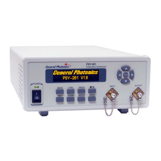
PSY-201 User Guide Section 2.0 Features 2.1 Front Panel and Optical Inputs The front panel of the PSY-201 is shown in Figure 4. Figure 4 PSY-201 front panel Front panel features: OLED display: Displays data and operation mode information. Power: Power on/off switch. -
Page 12: Fiber Connectors
PSY-201 User Guide Fiber Connectors The PSY-201 has two fiber connectors on the front panel for the optical input and output. The front panel adapters are universal connector interfaces (UCI), which feature a male-type adapter top piece that can be removed for direct access to the ferrule end for routine cleaning and maintenance without removing the entire adapter from the panel. -
Page 13: Rear Panel: Electrical And Remote Control Interfaces
The AC power plug, fuse, trigger and communication interface connectors are mounted on the rear panel, as shown in Figure 6. The PSY-201 includes RS-232, USB, Ethernet, and GPIB interfaces for remote control and communication. Control commands, USB driver installation instructions, and instructions for running control programs are located in the appendices. - Page 14 PSY-201 User Guide Expansion port pin definition: Figure 7 DB15 female connector on rear panel of PSY-201 Pin # Function Note 1,2,3,4,5,6,7 Ground Tracking trigger out Tracking status indicator. GPIO-4 If dSOP between target and current SOP is Within threshold:...
-
Page 15: Operation Instructions
1. Connect power cord and plug it into wall receptacle. Make sure the ground pin of the power cord is connected to earth ground. 2. Connect input and output fibers to the PSY-201. Make sure that the connector types match those of the instrument. It is important to clean the fiber connectors using industry standard procedures before connecting them. - Page 16 PSY-201 User Guide The PSY-201 has two main functions: polarization measurement and polarization control. Other support functions such as SOP reference, storage and system setup will also be discussed in this section. The operation modes will be described in the order of the corresponding front panel buttons, using the PolaView™...
- Page 17 PSY-201 User Guide The system setup menu is shown in Figure 10. SETUP Wavelength Units Power (dBm, mW) Integration Time Angle (deg, rad) Analog Outputs Trigger Amplitude (Voltage, π, radians) Communication Store Setup GPIB System Info TCP/IP System Restart DHCP...
- Page 18 PSY-201 User Guide GP-UM-PSY-201-11 Page 18 of 105...
-
Page 19: Functions
3.3 Functions The polarization measurement and control functions and setup options are described in more detail in this section. Polarization Measurement When the PSY-201 is first powered on, after initialization, its default mode is polarization measurement. Polarimeter function 0.132, -0.548, 0.826 DOP: 100.0... -
Page 20: Polarization Control
SOP by the PSY-201. Figure 11 (a) Input polarization pattern: triangle wave scramble at 1 Hz, taken over 20 sec. (b) Output polarization stabilized by PSY-201 against the same polarization-scrambled input. GP-UM-PSY-201-11 Page 20 of 105... - Page 21 PSY-201 User Guide Track SOP (Angle) This function allows the user to set and maintain a target SOP by specifying its spherical coordinates on the Poincaré sphere, as shown in Figure 12, rather than by specifying Stokes parameters. This representation is simpler in some respects, as it does not require vector normalization and can be easier to visualize.
- Page 22 PSY-201 does not apply any corrections. Once the output SOP goes outside the blue area, the PSY-201 will act to bring it back within the blue area. Therefore, as long as the tracking function is active, the PSY-201 will maintain the output SOP within the blue area.
- Page 23 PSY-201 User Guide dSOP Threshold Range: 0 to 180° from target SOP on Poincaré sphere Default: 0° Tracking status trigger: TTL level low = within threshold (SOP inside blue area) TTL level high = out of threshold (SOP outside blue area)
- Page 24 PSY-201 User Guide PSP: LP0 Step: 001.0° Circle trace icon Dwell: 00100ms [Run] PSP options: LP0, LP90, LP45, LP135, RHC, LHC Step range: 0.1 to 180° Dwell time: 10 to 65535 ms PSP=LP0° trace PSP=LP45° trace PSP=RHC trace LP0° axis LP45°...
- Page 25 Stored SOPs can be measured data or can be manually input by the user. Pol. Scrambling The PSY-201 can function as a variable speed polarization scrambler. There are four scrambling modes: Triangle, Discrete, Tornado, and Triggered. Scrambling control sequence: 1.
- Page 26 Figure 17 Discrete scramble, 1000 points/s after 30 seconds. Discrete Scrambling Output Trigger When in discrete scrambling mode, the PSY-201 sends a rising TTL pulse synchronized with each output SOP change to pin 14 of the DB15 expansion port on the rear panel. This output trigger signal can be used to synchronize to an external device.
- Page 27 PSY-201 User Guide Tornado Scrambling Tornado scrambling generates a continuous bidirectional spiral polarization trace with a quasi-uniform rate of SOP variation, which is useful in stress testing a device or an algorithm’s polarization tracking capabilities. The user-set scrambling rate is the number of complete circles traced out on the sphere per second.
- Page 28 To use this function, select “Trigger In” as the scrambling option. Type: Trigger In Connect external trigger (TTL signal) source to pin 13 on the DB15 expansion port connector on the rear panel of the PSY-201. - Pulse type: rising (0-5V) TTL pulse - Minimum pulse width: 100ns - Threshold voltage for TTL high: 2V.
- Page 29 PSY-201 User Guide The waveform graphic indicator appears when modulation is enabled, and indicates the waveform type for the selected channel. The unit indicator indicates the units for the parameter that is being set (e.g. Hz for frequency; V, π, or Rad for amplitude and offset).
- Page 30 PSY-201 User Guide Figure 20 Manual polarization control example The manual control screen is shown below: Channel indicators (V or Φ, depending on amplitude unit setting) V1: 000.0 V2: 015.0 Unit indicators V3: 032.6 V4: 100.0 (V, rad, or π, depending on amplitude unit setting) The display screen indicates the current control voltage or retardation for each channel.
-
Page 31: Track And ■/► Buttons
The TRACK button toggles the tracking function on and off. When tracking is enabled, the target indicator appears on the right side of the screen. When tracking is disabled, the PSY-201 restarts the function it was performing when tracking was enabled. -
Page 32: Reference
PSY-201 User Guide Reference The REF button allows the user to set a reference state (SOP, DOP, optical power), which can be used to monitor changes in these parameters. When the REF button is pressed while there is SOP information on the OLED display, e.g. from the measurement screen or the SOP Storage screen, the instrument will ask whether to set the displayed information as the reference. -
Page 33: Store
PSY-201 User Guide “Set. Ref.” allows the user to manually enter Stokes parameters, DOP and power for the reference state. The ◄► buttons move the cursor position, and the ▼▲ buttons change the value of the selected digit. The ENTER button confirms the new setting and moves the cursor to the next parameter. -
Page 34: Setup
SOP: 0.132, -0.548 , 0.826 # 01 DOP: 99.8% P: -3.00 dBm Update Clear ClearAll Setup The SETUP button brings up the setup menu for the PSY-201: 1. Wavelength 2. Units… ↓ 3. Integration Time ↑ 4. Analog Outputs ↓... - Page 35 Note: If the PSY-201’s operation wavelength does not match the wavelength of the light source, measurement and SOP generation accuracy can be affected. Built-in calibration matrices are spaced at 5nm intervals for the 1550nm PSY-201 and at 2nm intervals for the 1310nm PSY- 201.
- Page 36 The amplitude unit is the unit used to display the amplitude of the signals applied to the retarders of the polarization control unit inside the PSY-201. The amplitude can be displayed in volts, radians, or multiples of π radians. Radians or π units are calibrated to an accuracy of ±3%.
- Page 37 “OK” will appear on the right side of the screen to confirm the change. Analog Outputs The PSY-201 can output up to 4 monitor voltages that can be configured to monitor different parameters. The DB15 expansion port on the rear panel is used for the monitor voltages.
- Page 38 The trigger input uses the BNC connector on the rear panel of the instrument. For each trigger edge, the PSY-201 takes one set of data as set up in the oscilloscope mode of the PolaView software. To use the external measurement trigger, the trigger source in PolaView should be set to “External (TTL)”.
- Page 39 Reference SOP Figure 21 dREF trigger illustration With the dREF output trigger enabled, the PSY-201 outputs TTL low as long as the measured SOP is within the blue circle, and TTL high when the SOP is outside of the blue circle.
- Page 40 PSY-201 User Guide GPIB The GPIB option allows the user to set the GPIB address of the PSY-201. Use ◄► to move the cursor, ▲▼ to change values, and ENTER to confirm changes. Press SETUP to exit without saving changes. An “OK” indicator on the right side of the screen shows that the field has been updated.
- Page 41 PSY-201 for static IP addressing. Note: Even if no parameters were changed, it is necessary to select “Yes” on the update screen to set the PSY-201 for static IP addressing. The instrument retains its TCP/IP mode setting after power-off. However, for dynamic IP addressing, it is still necessary to go to TCP/IP setup and select “DHCP”...
- Page 42 It is important to match the command type setting to the command format being used. The PSY-201 will not recognize a command that does not match its command type setting. Use the ▲▼ buttons to change the setting and press ENTER to confirm. An “OK” will appear on the right side of the screen if the setting was changed.
- Page 43 PSY-201 User Guide Recall ID: # 0 Note: Default Store Setup Store Setup allows up to 9 user setups to be stored. The Note section can be configured to identify the setup alphanumerically. The Note is 5 characters long; characters can be digits 0-9 or letters A-H.
-
Page 44: Local
However, if the user wishes to access the front panel buttons while still interfaced to a computer, the LOCAL button can be used to unlock the front panel buttons. The PSY-201 will automatically switch back to remote mode as soon as it receives the next remote control command. -
Page 45: Troubleshooting
4. Make sure baud rate setting on instrument matches baud rate being used by control computer. 1. Make sure that the USB driver is installed before communicating via USB. 2. For the PSY-201, the USB interface is reserved for PolaView. The other interfaces can be used to communicate using the command lists. GP-UM-PSY-201-11... - Page 46 IP, the communication may be interrupted. PolaView 1. Make sure that the PSY-201 “Command Type” is set to SCPI and the EOS is set to <CR+LF>. PolaView will not work with other command settings. 2. Connect the PSY-201 to the control computer via USB. PolaView does not work with other communication interfaces.
-
Page 47: Specifications
PSY-201 User Guide Section 4.0 Specifications Optical Operating wavelength range 1480-1620 nm or 1280-1340nm Sampling rate Up to 4.0M samples/s Analog bandwidth 1MHz for input >−10 dBm SOP measurement/generation uncertainty ±0.25° (with user calibration) DOP measurement uncertainty ±2% (factory calibration) ±0.5% (user calibration) -
Page 48: Physical And Environmental
PSY-201 User Guide Communication Interfaces USB (PolaView only) RS-232, Ethernet, GPIB GPIB Address 1-30 RS-232 Baud Rate 110, 300, 600, 1200, 2400, 4800, 9600, 19200, 28800, 38400, 43000, 56000, 57600 USB data transmission rate 30MBps through USB 2.0 Analog output... - Page 49 PSY-201 User Guide Polarization Scrambling Type Trace Scrambling Rate Range Triangle Continuous 0.01 to 2000 ×2π/s Discrete Random, discontinuous points 0.01 to 20,000 points/s Tornado Continuous, spiral-type 0.01 to 2000 Rev/s pattern with rotating or fixed spin axis Triggered Triggered random state...
-
Page 50: Appendices
Appendices General Photonics provides the PolaView data display/analysis software for the POD-201 and PSY-201. Command lists are also provided for users to write their own control programs. The following appendices include the remote control command lists, setup for different control interfaces, and installation and application procedures for the control software. - Page 51 :SYSTem:COMMunicate:EOS? Query End Of String type for SCPI Response: < LF| CR| CR+LF> :SYSTem:COMMunicate:HSHake <1|0> Set/query handshake enable/disable status. When enabled, PSY-201 responds to SCPI commands with GP format command responses (e.g. *E00#). Default setting: 0 (disabled) :SYST:COMM:HSH 1 :SYSTem:GPIB:ADDRess <integer>...
- Page 52 PSY-201 User Guide :SYSTem:SERial:BAUDrate <integer> Set/query RS-232 baud rate. 110; 300; 600; 1200; 2400; 4800; 9600; 19200 28800; 9: 38400; 10: 43000; 11: 56000; 12: 57600 :SYST:SER:BAUD 6 Sample query response: 9600 Note: NET commands (IP, MASK, GWAY, NSERver) are used to set parameters for static IP addressing.
- Page 53 PSY-201 User Guide :CONFigure:SRATe:SOP <float> Set SOP sample rate Unit: Hz. Sampling rate range: 0.02 to 4000000 Hz. Examples: :CONF:SRAT:SOP 100000 :CONF:SRAT:SOP? :CONFigure:AMODe <1|0> Set/query integration time control mode. 0: auto integration time 1: manual integration time Examples: :CONF:AMOD 1...
- Page 54 PSY-201 User Guide Calibration Matrices :CALibration:WTYPe? Query whether the PSY-201 is a 1310 or 1550nm unit. :CALibration:CMATrix <integer>, Input custom matrix element. <float> integer: matrix element index 1 to 16: 1: m00, 2:m01, 3: m02, 4: m03, 5:m10, 6:m11, ….16:m33...
- Page 55 PSY-201 User Guide :OUTPut:ANALog<n>:MIN <float> Set output parameter min value for channel n. n = 1 to 4. Range: DOP: 0 to 100% POW: −60 to +15 dBm S1, S2, or S3: −1.00 to +1.00 dREF: 0 to 180.0° MIN < MAX :OUTPut:ANALog<n>:VLEVel...
- Page 56 PSY-201 User Guide :CONTrol:TSCan:DWELltime <integer> Set dwell time per point for trace scan: Range:10 to 65535 Unit: ms Default 100 Example: :CONTrol:TSCan:DWELltime 100 :CONTrol:TSCan:STATe <run|pause| Run/pause/continue/restart/exit trace continue|restart|exit> scan Query responses: on/pause/off :CONTrol:SSCan:DWELltime <integer> Set dwell time per point for stored-...
- Page 57 PSY-201 User Guide :CONTrol:CHANnel<n>:WAVeform:AMPLitude <float> Set modulation waveform amplitude for channel n n: 1 to 4. Ranges: 0 to 45V 0 to 4.71 Rad 0 to 1.49 Vpi. Units: V, RAD, or Vpi. Default: V :CONTrol:CHANnel<n>:WAVeform:FREQuency <float> Set modulation waveform frequency for channel n n: 1 to 4.
- Page 58 These commands are common to all GPIB-enabled devices. Command Parameters Response Description *IDN? <company>, Product identification query. Response: <model>, General Photonics PSY-201, V1.3-20141120, <firmware>,<serial> 155000000067 *RST Resets most functions to factory-defined conditions. Each command shows *RST value if the setting is affected. *TST? 0 or 1 This command queries the internal self-test when system initiates and returns a result.
- Page 59 A GP legacy format command list is available for users who may want to convert programs written for the PSY-101. New PSY-201 functions that were not available in the PSY-101 may not be covered in the GP format command list, so it is generally recommended that SCPI format commands be used to write new programs.
- Page 60 PSY-201 User Guide Table 4 GP Format Commands System Information Command Description Response *IDN? Query product number. *General Photonics,PSY-201,V1.3- 20141120,155000000067# or *Enn# if error *VER? Query Firmware Version. *V1.3-20141120# Version dependent *ADR nn# Set GPIB address *E00# if successful Range: 1 to 30...
- Page 61 PSY-201 User Guide Operation Mode *MOD? Query the current mode. *SOP#: SOP setting *ANG#: angle setting *SPE# special SOP (6 states) *TRA# trace scan *VCT# manual control *RAN# random scramble *SAW# triangle scramble *TOR# tornado scramble *TRG# triggered random SOP...
- Page 62 PSY-201 User Guide *TRA:SCN? Query the trace scanning speed *TRA:SCN 10# (dwell time = 10 ms) (dwell time per point, in ms) *TRA:STE n.f# Set the trace step size, in degrees *E00# if successful else *Enn# error Default 1° message...
- Page 63 PSY-201 User Guide Table 5 Command Response Codes No error (Correct command received) Undefined Command Parameter outside the allowed range Character string too long (>buffer limit) Power too high Power too low Error loading stored values Unable to store state Storage location invalid Recall location doesn’t exist...
- Page 64 Programming Notes for PSY-101 Users Although the GP format command list is provided for backward compatibility, because of changes to the structure of the PSY-201 relative to the PSY-101, there are some differences in how some of the commands work.
- Page 65 Figure 23 PSY-101 ellipse angles on Poincaré sphere In the PSY-201, the polarization ellipse angles have been relabeled. The azimuth angle is now denoted by AZM, and the ellipticity angle by ELPA. However, the range for AZM in the PSY- 201 is −90 to +90°, rather than 0 to 180°, as it was for the PSY-101.
- Page 66 Other differences in the command lists: 1. Manual control: In the PSY-201, the user can adjust the control voltages to 4 channels of the polarization controller, not 6. Any commands to control channels 5 or 6 need to be removed.
- Page 67 S1 axis S2 axis Figure 26 PSY-201 trace scan options: n = 0 (0°), 1 (45°), 2 (90°), 3 (135°), 4 (RHC), 5 (LHC). 0° and 90° trace the same pattern in opposite directions. 45° and 135° trace the same pattern in opposite directions RHC and LHC trace the same pattern in opposite directions (around the equator) 5.
-
Page 68: Appendix 2.0 Rs-232 Connection And Setup
PSY-201 User Guide Appendix 2.0 RS-232 connection and setup 1. The RS-232 connector on the rear panel of the PSY-201 is a DB9 male connector. Use a straight (not cross connected) RS-232 cable with DB9 female connectors to connect the PSY-201 to the control computer. -
Page 69: Appendix 3.0 Usb Connection And Setup
Run the Setup file on the shipping cd to install the PolaView software. This will also copy the USB drivers to the control computer. After the setup is finished, connect the PSY-201 to the computer with a USB cable and power on the PSY-201. The USB driver should install automatically (follow instructions on the installation wizard). -
Page 70: Appendix 4.0 Ethernet Setup
DHCP server PSY-201 Switch PSY-201 Figure 28 Direct connection: PSY-201 to PC Figure 29 Connection with DHCP server Once the physical connections are established, the instrument’s Ethernet configuration can be set up from the front panel. GP-UM-PSY-201-11... - Page 71 IP addressing and requests a dynamic IP address from the DHCP server. Selecting “Static IP” allows the user to set the PSY-201 for static IP addressing and to set the static IP address, net mask, gateway, and name server. See section 3.3 for a more detailed description. Note that even if no settings were changed, it is necessary to go through all of the static IP setup screens and select “Yes”...
-
Page 72: Appendix 5.0 Gpib Setup And Control
Connect the instrument to the computer with a GPIB cable. After determining/setting the PSY-201’s GPIB address, enter the GPIB address in the communication program being used. The instrument will then be ready to receive commands. The command lists is given in Appendix 1. -
Page 73: Appendix 6.0 Polaview Data Display/Analysis Program
⎦ where V are analog output voltages from the polarimeter, M is a calibration matrix, and S are the Stokes parameters corresponding to V The PSY-201 provides normalized Stokes parameters defined as follows: is the measured power. norm norm norm... - Page 74 PSY-201 User Guide , and s are the Stokes parameters normalized to the surface of the sphere. They satisfy the normalization condition = 1. DOP: Degree of polarization of light norm DOP = dREF: The angle between the current SOP and the reference SOP −...
-
Page 75: Instrument Compatibility
The following sections refer to PolaView V2.501 and above. Instrument Compatibility The PolaView software can be used with either the POD-201 polarimeter or the PSY-201 polarization synthesizer. When the program is started, it detects which instrument is connected and enables or disables functions accordingly. -
Page 76: Software Installation
The software can be removed from the “Add or Remove Programs” section of the control panel. Setup 1. Connect the POD-201 or PSY-201 to the control computer with a USB cable. Power on the instrument. 2. Press the SETUP button on the front panel, and go to the communication setup menu. Make sure that the instrument’s Comm Type setting is set to SCPI, and the EOS is set to CR + LF. - Page 77 PSY-201 User Guide Figure 31 Poincaré Sphere display Parameter display selection Sphere display mode uses continuous data acquisition. The data acquisition process begins and data points appear on the sphere when the user clicks the “Start” button. The process runs until the “Stop”...
-
Page 78: Oscilloscope Display
PSY-201 User Guide sphere in or out. Both the house button at the center bottom of the screen and the “Home” button immediately above the “Start” button return the sphere to its default position and size. The sphere display buffers 100,000 points. Therefore, if the sphere is rotated, only the most recent 100,000 points will be retained. -
Page 79: Option Menu
PSY-201 User Guide corresponding oscilloscope trace and data display area. Parameters that can be monitored include S0 (power), s1, s2, s3 (normalized Stokes parameters), Azimuth, Ellipticity, DOP (degree of polarization), DLP (degree of linearity), DCP (degree of circularity) and dREF (angle variation of the current point from the reference point). - Page 80 PSY-201 User Guide Wavelength The wavelength setting determines the calibration matrix used for SOP measurement. Wavelength range: 1480-1620nm or 1280-1340nm. PolaView auto-senses the wavelength range of the instrument to which it is connected. Built-in calibration matrix wavelength spacing is 5nm for 1550nm instruments and 2nm for 1310nm instruments.
- Page 81 PSY-201 User Guide Note that the sampling rate is not necessarily the same as the data capture rate. The data capture rate is the rate at which SOPs are written to a file or displayed on-screen. Since, under some circumstances, not every sampled point is recorded, Data capture rate ≤...
- Page 82 PSY-201 User Guide Trace Sensitivity range: 0, 0.5 to 10 degrees. Trace Sensitivity = 0: Variable capture rate is disabled, and data capture rate = SOP sampling rate. Trace Sensitivity ≥ 0.5: Data capture rate increases with input ΔSOP rate, and is limited by the SOP sampling rate.
- Page 83 PSY-201 User Guide For the settings in this example, the data capture rate and dSOP (angle difference between consecutive captured SOPs) varies as follows: C = capture rate dSOP (degrees) Δ = Change in input SOP Δ (kpoints/s) (kdegrees/s) ≤ 0.5 =0.1...
- Page 84 PSY-201 User Guide Trigger Settings (Oscilloscope Mode only) The Trigger Settings window allows the user to set up parameters for triggered measurement in oscilloscope mode. Trigger Mode options: free run, repeat, single shot. Free Run: Continuous data collection; no triggered operation. In this mode, the oscilloscope display refreshes at a rate of 30 frames/s.
- Page 85 PSY-201 User Guide Type: Defines what constitutes a trigger event for each source. For source = external TTL, type options include rising edge, falling edge, and rising and falling edge. For source = dREF, type options include rising edge, falling edge, rising and falling edge, above threshold or below threshold.
- Page 86 The delay feature is useful in cases where the POD-201 or PSY-201 is used to observe the SOP at the end of a system with a long optical path. For example, if light takes 10ms to travel...
- Page 87 PSY-201 User Guide For the preset SOPs (pole points), the SOP selection determines the Stokes parameters, the power reference is set at 1mW, and the DOP reference is set at 100%. For “current SOP”, the current measured Stokes parameters, power level, and DOP are set as the reference.
- Page 88 PSY-201 User Guide The S-parameters initially entered do not have to be normalized. Clicking the “Normalize” button normalizes the Stokes parameters to the surface of the Poincaré sphere. Gain Control The gain control window allows the user to set the gain control mode to automatic (gain level may vary with power level) or to manually set a fixed gain level (0 to 18).
- Page 89 The calibration setup window allows the user to select the polarimeter calibration matrix to be used for SOP measurement. Factory Matrix: The POD-201 or PSY-201 comes with a set of factory-generated calibration matrices for wavelengths in its operating wavelength range. If “Factory Matrix” is selected, then the wavelength setting determines the built-in calibration matrix that is used for measurement.
- Page 90 Creation of a new calibration matrix requires measurement of at least 50 different SOPs. Click “OK” on the notification window button. Click “Start” to begin matrix generation. PolaView uses the PSY-201’s triangle scrambling function at a scrambling rate of 3 × 2π/s to create the required set of diverse SOPs.
- Page 91 PSY-201 User Guide Once the measurement is completed and the matrix is generated, the user will be prompted to name and save the matrix file. The file will have file extension .DAT but can be opened as a text file for viewing.
-
Page 92: Measurement Menu
PSY-201 User Guide Measurement Menu The Measurement Menu lists available measurement options. Poincaré Sphere This option displays data on a Poincaré Sphere. It is the default data display mode. GP-UM-PSY-201-11 Page 92 of 105... - Page 93 PSY-201 User Guide Oscilloscope This option displays data on a virtual oscilloscope window and allows for triggered measurement. GP-UM-PSY-201-11 Page 93 of 105...
- Page 94 PSY-201 User Guide Stream to File The “stream to file” function saves measured data to one or more text files, as well as displaying it on the sphere. Selecting this option from the Measurement menu causes the “stream to file” control pane to appear on the left side of the screen.
- Page 95 PSY-201 User Guide Interval: The interval between recorded points, in Timed mode, in ms. Range: 0 to 50,000 ms. File Path: Specify the file path for the data to be saved. Data will be streamed to that location as it is collected.
- Page 96 PSY-201 User Guide Select the desired data file and click “Open”. The Replay control pane will appear on the left side of the screen. Loading Speed: Select the relative speed for playback. x0.01 slow down by a factor of 100 x0.1...
- Page 97 PSY-201 User Guide Note that the “total time length” and “current time” boxes use the actual time stamps for recorded data. Therefore, the speed setting only affects the update speed of the counter. Markers This option allows the user to mark points on the sphere and measure the angles between marked points or between marked points and a reference SOP.
- Page 98 PSY-201 User Guide Buttons: Insert: Add a new marker at the currently measured SOP. Delete: Delete selected or most recent marker. Hide: Hide markers. Save: Save marker information to a text file. Load: Load a previously saved set of markers for display.
- Page 99 PSY-201 User Guide through the system, expressed in dB. The crosstalk measured at any point in the system is the result of the cumulative effects of the polarization properties of the light source (light not fully polarized or not linearly polarized), misalignments at fiber connections or splices, and propagation through the fiber itself up to the measurement point.
- Page 100 PSY-201 User Guide the circle is defined by the optical (slow) axis of the PM fiber, and the radius of the circle by the misalignment of the light to the slow axis, as shown in Figure 38. α Figure 38 Poincaré Sphere illustration of polarization state rotation of output light from a PM fiber...
-
Page 101: Control Menu
PER Measurement Using the POD-201 or PSY-201 1. Connect the system under test to the POD-201 or PSY-201. Make sure that all of the fiber sections except the section under test are immobilized. - Page 102 Tornado, rotating axis Tornado, fixed axis The scrambling control pane allows the user to activate the PSY-201’s triangle, discrete, or Tornado scrambling functions from within PolaView. Select the scrambling mode, scrambling rate, and for Tornado mode, axis rotation option, then click “Enable” to begin scrambling.
- Page 103 PSY-201 User Guide The “Track” button is the functional equivalent of the TRACK quick key on the PSY-201 front panel. However, in PolaView, “Untrack” only disables active tracking. It does not restart any polarization control functions interrupted by invoking the TRACK function.
- Page 104 Unlike the front panel control, the PolaView waveform control allows the waveforms for individual channels to be enabled/disabled independently. The “Track” button is the functional equivalent of the TRACK quick key on the PSY-201 front panel. However, in PolaView, “Untrack” only disables active tracking. It does not restart any polarization control functions interrupted by invoking the TRACK function.
- Page 105 Basis SOPs: H, V, +45, −45, RHC, LHC The “Track” button is the functional equivalent of the TRACK quick key on the PSY-201 front panel. However, in PolaView, “Untrack” only disables active tracking. It does not restart any polarization control functions interrupted by invoking the TRACK function.
Need help?
Do you have a question about the PSY-201 and is the answer not in the manual?
Questions and answers