Table of Contents
Advertisement
Quick Links
Advertisement
Table of Contents

Subscribe to Our Youtube Channel
Related Manuals for Barco FLX-24


Summary of Contents for Barco FLX-24
- Page 1 FLX-24 Installation manual R59770420/00 21/12/2009...
- Page 2 Barco Inc. Media and Entertainment Division 11101 Trade Center Drive, Rancho Cordova, California 95670, USA Phone: +1 916 859-2500 Fax: +1 916 859-2515 E-mail: folsomsales@barco.com Visit us at the web: www.barco.com Barco nv Media & Entertainment Division Noordlaan 5, B-8520 Kuurne Phone: +32 56.36.82.11...
- Page 3 The period of guarantee begins on the date of transfer of risks, in the case of special systems and software on the date of commissioning, at latest 30 days after the transfer of risks. In the event of justified notice of complaint, Barco can repair the fault or provide a replacement at its own discretion within an appropriate period.
- Page 4 Trademarks Brand and product names mentioned in this manual may be trademarks, registered trademarks or copyrights of their respective holders. All brand and product names mentioned in this manual serve as comments or examples and are not to be understood as advertising for the products or their manufacturers.
-
Page 5: Table Of Contents
Index........................71 R59770420 FLX-24 21/12/2009... - Page 6 Table of contents R59770420 FLX-24 21/12/2009...
-
Page 7: Safety
Read this chapter attentively. It contains important information to prevent personal injury while installing the FLX-24. Furthermore, it includes several cautions to prevent damage to the FLX-24 parts. Ensure that you understand and follow all safety guidelines, safety instructions and warnings mentioned in this chapter before installing the FLX-24. After this chapter, additional “warnings” and “cautions”... -
Page 8: Safety Guidelines
Structural & mounting components should be kept dry, clean, lubricated (only if recommended), coated properly, and otherwise maintained in a manner consistent with part design. Barco products must be used in a manner consistent with their design and inspected on a routine basis for security, wear, deformation, corrosion and any other circumstances that may affect the load handling capability of the part. -
Page 9: Important Safety Instructions
Use only with systems or peripherals specified by the manufacturer, or sold with the apparatus. Use caution during lifting/moving or transporting to avoid damage by possible tipping. • All locking mechanisms should function properly. Any malfunction locking mechanism of an FLX product should be replaced prior to product installation. R59770420 FLX-24 21/12/2009... -
Page 10: Important Warnings
Risk of electric shock / Risk of fire: To protect against risk of fire by overloading of power cables, MAXIMUM 256 FLX-24 pixels may be connected to one output port of the FLX-HUB and MAXIMUM 8192 FLX-24 pixels may be connected to one power output socket of the FLX Power chassis DPR-2700. -
Page 11: Important Warnings For The Flx Power System Dpr-2700
Delta connection: 6 AWG L1/L2/L3 16. The FLX Power System DPR-2700 is only for connection with the Barco FLX-HUB. 17. A readily accessible disconnect device shall be incorporated in the building installation wiring. The disconnect device shall be a circuit breaker or a branch fuse according to the following rating: maximum 60A with 3 poles L1 L2 L3. -
Page 12: Proper Usage
FLX display. • Only Barco cables specified to be used with the FLX products are to be used to connect components in an FLX display. Further, care must be taken to connect signal only according to the installation manual. -
Page 13: Installation Requirements
2. Installation requirements 2. INSTALLATION REQUIREMENTS About this chapter This chapter enumerates the mechanical requirements for the FLX-24 pixel, the electrical requirements to power up the FLX creative LED display and the system requirements to run the control software efficiently. Overview •... -
Page 14: Mechanical Requirements
There are two solutions to align the FLX-24 pixels easily. The first solution is using a support plate with a (keyhole) cutout of the top side of the FLX-24 pixel. Note that the top side of the FLX-24 pixel has a lid which can be used to orient all pixels equally. The drawing below shows the cutout dimensions (in mm) required for the top side of the FLX-24 pixel. -
Page 15: Electrical Requirements
Electrical requirements for the FLX-24 pixel The power for the FLX-24 pixels is delivered by the FLX Power rectifiers DPR-2700 installed in the FLX Power Chassis DPR-2700. One FLX Power chassis DPR-2700, fully equipped with six rectifiers each delivering 2700 watt, consumes maximum 16200 watt. -
Page 16: System Requirements For The Control Software
SXGA resolution (1280 x 1024) with 32 Mb video memory Serial communication port Ethernet connection • Software Windows XP Professional or Windows Vista 1. It runs on Windows 2000 but when problems are discovered, Barco does not deliver any support R59770420 FLX-24 21/12/2009... -
Page 17: Components Of An Flx Display System
Note that some FLX components have dedicated manuals to where this chapter will refer to for more detailed infor- mation. Overview • System overview • FLX-24 Pixel • FLX-NNI Controller • FLX-NNI Controller user interface • FLX-HUB • FLX power system DPR-2700 • DX-700 Digitizer • DX-100 Digitizer • Control software R59770420 FLX-24 21/12/2009... -
Page 18: System Overview
3. Components of an FLX display system System overview Block diagram of an FLX-24 creative display DX-700 Director Toolset (Local PC) Digitizer FLX-NNI CTRL FLX-NNI CTRL FLX-NNI CTRL Control center Power center Indoor Outdoor FLX-HUB FLX-HUB FLX-HUB FLX-HUB Creative display... - Page 19 FLX-Power Extension Cable. Maximum cable length of 50 meter between PSU (DPR-2700) and FLX-HUB. FLX-Power Splitter Cable. 1 to 4. FLX-24 converter cable and optional FLX-HUB output extension cable. Maximum 20 meter extension cable between FLX-HUB and connector string with FLX-24. FLX-24 Connector string. Strings can be interconnected up to 256 pixels.
-
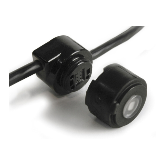
Page 20: Flx-24 Pixel
Introduction The FLX-24 pixel is a compact, high quality LED pixel module that can be combined with a wide variety of specifically designed carriers (mechanical structures) into any shape you desire. The FLX-24 pixel has a 24 mm diameter and one full-color LED. The housing of the FLX-24 pixel has an IP66 rating. - Page 21 Keep the FLX-24 pixel upon the socket for storing. Connectivity The FLX-24 Pixel can be plugged into a molded FLX-24 socket on a cable or into a FLX-24 socket witch is mounted on a strip (PCB board). Barco offers two standard connector strings and two standard strips: •...
- Page 22 3. Components of an FLX display system The connector string and strips can be used together in the same FLX-24 pixel string. The plugs of the connector strings and strips are from the bayonet mount locking mechanism. Up to 256 FLX-24 pixels can be connected in one string. Each FLX-24 pixel string must be connected via an FLX-24 converter cable (R9899553B8: 8 pieces) with one of the output ports of the FLX-HUB.
- Page 23 3. Components of an FLX display system Image 3-10 FLX-24 data extension cable (R9899552: 1 piece of 2 meter; R9899561: 1 piece of 5 meter) R59770420 FLX-24 21/12/2009...
-
Page 24: Flx-Nni Controller
HDMI input or output ports such as an LCD display or a DVD player, with an FLX-NNI Controller unit or a DX-700 Digitizer. Such a connection could be harmful for both Barco devices as for the standard HDMI devices. Parts location of the FLX-NNI Controller Image 3-11 data input port. - Page 25 Image 3-13 Barco offers three lengths of NNI cables (HDMI plugs with latches) to connect the FLX-NNI Controller units with each other. The different lengths are 1 meter, 5 meter and 10 meter. Note that one NNI cable of 1 meter is delivered with the FLX-NNI Controller.
-
Page 26: Flx-Nni Controller User Interface
The left side This controller HUBs shows the path of the menu which is “BARCO FLX” for the root menu. Address: The right column shows a list with sub menu items. The item marked with a triangle ►... - Page 27 TIP: Use the first FLX-NNI Controller unit in the stream to set the pattern, contrast or gamma. Address: BARCO FLX ► All controllers ► Patterns ► Pattern off This menu allows you to activate one of the test patterns for this...
- Page 28 The last item in the list is ’Back’ which can be used to go to the ► Back Address: previous menu. BARCO FLX ► This controllers ► Local patterns ► Pattern off This menu allows you to activate one of the local test patterns for BARCO FLX this FLX-NNI Controller.
- Page 29 Back address. So, it’s recommend to start the address numbering from Address: 1 or higher. BARCO FLX ► This controller ► LCD contrast ► Up 10 This menu allows you to set the LCD contrast of this FLX-NNI BARCO FLX Controller.
- Page 30 Controller and thus remains available for restoring. LOADING! PLEASE WAIT ... This message will appear during the ’Restore’ action. BARCO FLX ► This controller ► String config ► Default config This menu allows you to start loading the default configuration. BARCO FLX...
- Page 31 3. Components of an FLX display system BARCO FLX ► This controller ► Restore settings The ’Restore settings’ is a very useful option to get back all the BARCO FLX This option allows settings of the FLX-NNI Controller in case of a replacement. The...
- Page 32 01.00.0 Backup: 01.00.0 Pixel type: FLX-24 Pixels: 256,128,128,64,64,64,64,4 BARCO FLX ► HUBs ► Power off This option allows you to switch off the power of all FLX-HUB BARCO FLX POWER OFF HUBs ALL HUBS units connected with this FLX-NNI Controller.
- Page 33 FLX-HUB units connected with the FLX-NNI Controller unit. HUB update error This message appears in case the update process of all FLX-HUB units connected with the FLX-NNI Controller unit was successful. HUB update done R59770420 FLX-24 21/12/2009...
-
Page 34: Flx-Hub
Introduction The FLX-HUB is the interface between the FLX-24 pixel strings, the FLX-NNI Controller and the DPR-2700 power system. Power from the DPR-2700 power system and data from the FLX-NNI Controller are brought together on the FLX-HUB for further distribution to the FLX-24 pixel strings. - Page 35 Rental mounting bracket (R9863020: 2 pieces). Fixed mounting bracket (R9863030: 4 pieces). Cables used with the FLX-HUB See the chapters about FLX-NNI Controller, DPR-2700 power system and FLX-24 pixel for information of cables used with the FLX-HUB. FLX-HUB input port diagnostic LED...
- Page 36 FLX-HUB. The diagnostic LEDs of the other output ports are lighting red or yellow. There is no connection with an FLX-24 Connect an FLX-24 pixel string with this pixel string detected on this output port of output port of the FLX-HUB.
- Page 37 3. Components of an FLX display system FRONT VIEW BACK VIEW Signal Connector FRONT VIEW BACK VIEW Image 3-24 R59770420 FLX-24 21/12/2009...
-
Page 38: Flx Power System Dpr-2700
DPR-2700 has two power output ports, so one FLX Power System DPR-2700 can power maximum 16384 FLX-24 pixels. This large number of pixels can only be powered in case the total length of the power cables, from the power output port to the last FLX-24 pixel in the connector string, is limited. - Page 39 Power cables and power splitter cables Barco offers two lengths of FLX power cables, 5 and 25 meter. Only these power cables and the custom made power cables, which meets the requirements as described below, may be used to connect the FLX-HUB with the FLX Power System DPR-2700 (or other Barco approved power system for FLX).
- Page 40 0 – 95 % UV resistant All weather resistant Color Black Flammability rating VW-1 Hazardous materials RoHS compliant Approvals UL / CSA Outer markings Name UL approved with file number or logo Maximum temperature voltage rating VW-1 R59770420 FLX-24 21/12/2009...
- Page 41 Only FLX power cables can be used which are made by trained and qualified technicians. ARNING To protect the FLX power cables for overheating maximum 4 FLX power cables may be bundled together. Futhermore, the FLX power cables must always be used unwound. R59770420 FLX-24 21/12/2009...
- Page 42 1, 3, 11, 13 (spare) J1, J2, J3, J4 0V rail 5, 7, 9, 15 -54V FUSE No.3 4, 6, 8, 16 (spare) J1, J2, J3, J4 2, 10, 12, 18 -54V FUSE No.6 EARTH (GND) J1, J2, J3, J4 R59770420 FLX-24 21/12/2009...
-
Page 43: Dx-700 Digitizer
DX-700 Digitizer General The DX-700 is a multi-window video processor designed for use as a versatile front-end to all Barco LED products. The digitizer processes (image processing, conversion and conditioning) all source signals for digital distribution to every tile. •... -
Page 44: Dx-100 Digitizer
General The DX-100 is a multi-window video processor designed for use as a versatile front-end to the FLX displays of Barco only. The digitizer processes (image processing, conversion and conditioning) all source signals for digital distribution to every FLX-NNI Con- troller,supported via the NNI interface on the system’s NNI Output Module... -
Page 45: Control Software
General The control software is designed as a graphic user interface (GUI) and can be used to control and configure the digitizer as well as the Barco LED wall via a PC (e.g. Director toolset). Minimum required software version: 1.06 Image 3-35 Control software “Director toolset”. - Page 46 3. Components of an FLX display system R59770420 FLX-24 21/12/2009...
-
Page 47: Installation Procedures
This chapter contains general installation procedures for the FLX display. Overview • Set up process of an FLX display • Overview cabling FLX system with FLX-24 pixels • Mounting the FLX-24 pixel in its socket • Mounting the rental bracket on the FLX-HUB •... -
Page 48: Set Up Process Of An Flx Display
Take into account that one FLX Power System DPR-2700 unit can power maximum 16384 FLX-24 pixels. Use a power splitter cable to split the power output in to four outputs. See chapter "FLX power system DPR- 2700", page 34. -
Page 49: Overview Cabling Flx System With Flx-24 Pixels
FLX Power Splitter Cable. From 1 to 4. FLX-HUB output extension cable. Up to 20 meter till FLX-24 converter cable. FLX-24 converter cable. Required between each FLX-HUB output port and first FLX-24 connector string. FLX-24 connector string. Up to 256 FLX-24 pixels per FLX-HUB output port. -
Page 50: Mounting The Flx-24 Pixel In Its Socket
“stress cracking”. 2. Approach the socket with the FLX-24 pixel. Make sure that the three positioning pins (reference 3) of the FLX-24 pixel are aligned with mounting holes (reference 1) on the socket. -
Page 51: Mounting The Rental Bracket On The Flx-Hub
2. Do you want to use a rigging clamp to install the FLX-HUB? If yes, proceed with step 3. 3. Install the rigging clamp on the rental bracket as illustrated. Note the rigging clamp must has M10 thread. Image 4-4 R59770420 FLX-24 21/12/2009... - Page 52 4. Installation procedures 4. Secure the rigging clamp by fastening the bolt (reference 3 image 4-4). R59770420 FLX-24 21/12/2009...
-
Page 53: Mounting The Fixed Bracket On The Flx-Hub
1. Place the fixed bracket into position as illustrated and fasten with four screws. Use a PH1 Phillips screwdriver the fasten the screws (reference 1). Make sure that each screw is provided with a spring washer (reference 2). Image 4-5 R59770420 FLX-24 21/12/2009... -
Page 54: Mounting The 19" Rack Bracket On The Flx-Hub
1. Place the 19” rack bracket upon the two FLX-HUB units as illustrated. Fasten each FLX-HUB with four screws (reference 1) using a PH1 Phillips screwdriver. Make sure that each screw is provided with a lock washer (reference 2). Image 4-6 2. Now the FLX-HUB assembly can be installed in a standard 19” rack. R59770420 FLX-24 21/12/2009... -
Page 55: Installing The Rj45 Ip66 Protection Shells
6. Slide the long sealing rubber (part 5) against the RJ45 plug and then slide part 3 against the long sealing rubber. Image 4-9 7. Place part 6 over the RJ45 plug and fasten with part 7. Image 4-10 8. Fasten the back end of the shell with part 1. R59770420 FLX-24 21/12/2009... - Page 56 4. Installation procedures Image 4-11 R59770420 FLX-24 21/12/2009...
-
Page 57: Maintenance
5. Maintenance 5. MAINTENANCE About this chapter This chapter contains some maintenance information about the FLX-24 pixel and the FLX-HUB which can be performed by the persons who do the installation. Overview • Cleaning the FLX-24 pixel • Cleaning the FLX-HUB •... -
Page 58: Cleaning The Flx-24 Pixel
FLX-24 connector string. How to clean the FLX-24 pixel? 1. Plug the FLX-24 pixel(s) on the connector string to seal off the power/data socket of the pixel. This is necessary to protect the electronic parts inside the unit. 2. Clean the outside of the FLX-24 pixel with a soft brush and some water. -
Page 59: Cleaning The Flx-Hub
3. Clean the outside of the FLX-HUB with a soft brush and some water. Caution: Do not submerge the FLX-HUB into water or other liquids. 4. Wipe dry the FLX-HUB using a clean cloth. 5. Disconnect the FLX power cable and the FLX data cable from the FLX-HUB. R59770420 FLX-24 21/12/2009... -
Page 60: Replacing The Flx-Nni Controller
8. Switch on the power of the FLX-NNI Controller and start the ’Restore settings’ procedure within 5 minutes. Do this by brows- ing in the user interface of the FLX-NNI Controller to BARCO FLX ► This controller ► Restore settings and then start the procedure by selecting the option ►... -
Page 61: Dimensions
This chapter contains mechanical drawings with the most important dimensions of the FLX components. Overview • Dimensions of the FLX-24 pixel • Dimensions of the FLX-24 adapter cable • Dimensions of the FLX-S Strips • Dimensions of the FLX-NNI Controller •... -
Page 62: Dimensions Of The Flx-24 Pixel
A. Dimensions A.1 Dimensions of the FLX-24 pixel Dimensions Ø23,03 Ø19 Ø10,7 6° Ø24 4° Image A-1 Dimensions given in millimeters. R59770420 FLX-24 21/12/2009... -
Page 63: Dimensions Of The Flx-24 Adapter Cable
A. Dimensions A.2 Dimensions of the FLX-24 adapter cable Dimensions FLX-24 adapter cable Image A-2 Dimensions given in millimeters. R59770420 FLX-24 21/12/2009... -
Page 64: Dimensions Of The Flx-S Strips
A.3 Dimensions of the FLX-S Strips Dimensions FLX-S25 Strip 312,5 312,5 31 x 25 = 775 Image A-3 Dimensions given in millimeters. Dimensions FLX-S50 Strip 312,5 312,5 15 x 50 = 750 Image A-4 Dimensions given in millimeters. R59770420 FLX-24 21/12/2009... -
Page 65: Dimensions Of The Flx-Nni Controller
A. Dimensions A.4 Dimensions of the FLX-NNI Controller Dimensions Image A-5 Dimensions given in millimeters. R59770420 FLX-24 21/12/2009... -
Page 66: Dimensions Of The Flx-Hub
A. Dimensions A.5 Dimensions of the FLX-HUB Dimensions 36,35 215,17 80,5 14,8 Image A-6 Dimensions given in millimeters. R59770420 FLX-24 21/12/2009... -
Page 67: Dimensions Of The Flx-Hub Fixed Bracket
A. Dimensions A.6 Dimensions of the FLX-HUB fixed bracket Dimensions Ø6,5 (4x) Ø10,5 (2x) 69.5 87.5 Image A-7 Dimensions given in millimeters. R59770420 FLX-24 21/12/2009... -
Page 68: Dimensions Of The Flx Power Chassis Dpr-2700
A. Dimensions A.7 Dimensions of the FLX Power Chassis DPR-2700 Dimensions 435,4 482,6 465,2 349,4 340,3 Image A-8 Dimensions given in millimeters. R59770420 FLX-24 21/12/2009... -
Page 69: Specifications
B. Specifications B. SPECIFICATIONS Overview • FLX-24 specifications • Weight of individual parts of an FLX system R59770420 FLX-24 21/12/2009... -
Page 70: Flx-24 Specifications
B. Specifications B.1 FLX-24 specifications Specifications Access front or rear Brightness 3.000 mcd Calibration batch-to-batch correction Color depth 16-bit/color 16 pixels, 130 mm pitch, interconnectable Default cable string 64 pixels, 130 mm pitch, interconnectable Diameter 24 mm Height 31 mm (inl. socket) -
Page 71: Weight Of Individual Parts Of An Flx System
B. Specifications B.2 Weight of individual parts of an FLX system Weight of individual parts 30 g. FLX-24 pixel (incl. socket and 130 mm cable) FLX-HUB 1,5 kg. FLX-NNI Controller 3,7 kg. FLX Power Chassis DPR-2700 (without rectifiers) 15 kg. - Page 72 B. Specifications R59770420 FLX-24 21/12/2009...
-
Page 73: Order Info
C. Order info C. ORDER INFO About this chapter This chapter contains the order numbers of all available FLX parts. Overview • Order info list R59770420 FLX-24 21/12/2009... -
Page 74: Order Info List
R9899550 FLX-24 Connector string 64 connections at 160 mm pitch Bag of 1. R9899555B16 FLX-S25 Strip for 32 FLX-24 pixels at 25 mm pitch Box of 16 pieces. R9899556B16 FLX-S50 Strip for 16 FLX-24 pixels at 50 mm pitch Box of 16 pieces. -
Page 75: Index
46–47, 49–50 19” bracket Fixed bracket FLX-24 Rental bracket Default config Digitizer 39–40 Dimensions 57–64 DPR-2700 Fixed bracket Navigation FLX-24 adapter cable FLX-24 pixel FLX-HUB FLX-NNI Controller Order info 69–70 FLX-S Strips Overview DPR-2700 34, 64 Control software Dimensions Patterns... - Page 76 Index This controller Weight Parts User interface R59770420 FLX-24 21/12/2009...
Need help?
Do you have a question about the FLX-24 and is the answer not in the manual?
Questions and answers