
Related Manuals for BW GasAlertMicro 5

Summary of Contents for BW GasAlertMicro 5
- Page 1 GasAlertMicro 5 and GasAlertMicro 5 PID , CO, H S, PH , SO , Cl , NH , NO , HCN, ClO , VOC, and Combustibles 1, 2, 3, 4, and 5 Gas Detectors User Manual...
-
Page 2: Table Of Contents
Table of Contents Title Page Introduction............................1 Contacting BW Technologies........................ 2 Safety Information - Read First ......................2 Getting Started ............................6 Activating the Detector ........................10 Self-Test..........................10 Self-Test Pass ........................17 Self Test Fail........................17 Battery Test.......................... 17 Datalogger Operation ...................... - Page 3 GasAlertMicro 5 and GasAlertMicro 5 PID User Manual Low Battery Alarm........................42 Automatic Shutdown Alarm ....................42 Calibration and Setting Alarm Setpoints .....................42 Guidelines ..........................42 Diagnostics Protection ......................43 Applying Gas to the Sensors ....................44 Calibration Procedure ......................44 Attaching the Accessories........................57 Installing the Pump Module ....................57 Attaching the Sample Probe ....................58...
- Page 4 List of Tables Table Title Page Gases Monitored ........................1 International Symbols ......................5 GasAlertMicro 5 and GasAlertMicro 5 PID Detector ............. 7 Display Elements ........................8 Pushbuttons ........................... 9 Alarms..........................35 Computed Gas Exposures ....................38 Gas Alarm Setpoints......................39 OSHA Sample Factory Alarm Setpoints................
- Page 5 List of Figures Figure Title Page GasAlertMicro 5 and GasAlert Micro 5 PID Detector ............7 Display Elements ........................8 Applying Gas to the Sensors ....................44 Installing the Pump Module ....................57 Attaching the Sample Probe....................58 Installing and Removing the MMC/SD ................60 Replacing the Batteries .......................
- Page 6 GasAlertMicro 5 and GasAlertMicro 5 PID User Manual CAUTION: FOR SAFETY REASONS, THIS EQUIPMENT MUST BE OPERATED AND SERVICED BY QUALIFIED PERSONNEL ONLY. READ AND UNDERSTAND THE INSTRUCTION MANUAL COMPLETELY BEFORE OPERATING OR SERVICING. GasAlertMicro 5 Multi-Gas Detector Standard instrument is equipped with integral concussion- proof boot and internal vibrator alarm.
-
Page 7: Introduction
Safety Information before using the detector. explosive limit (% LEL) field selectable for: percent by volume The GasAlertMicro 5 gas detector (“the detector”) warns of methane 0-5.0% v/v hazardous gas at levels above user-selectable alarm parts per million (ppm) Carbon monoxide (CO) setpoints. -
Page 8: Contacting Bw Technologies
GasAlertMicro 5 and GasAlertMicro 5 PID User Manual Safety Information - Read First Use the detector only as specified in this manual, otherwise the protection provided by the detector may be impaired. International symbols used on the detector and in this manual are explained in Table 2. - Page 9 BW recommends at least once every 180 days (6 months). ⇒ BW recommends to “bump test” the sensors before each day’s use to confirm their ability and response to gas by exposing the detector to a gas concentration that exceeds the high alarm setpoints. Manually verify that the audible and visual alarms are activated.
- Page 10 ⇒ Protect the PID sensor from exposure to silicone vapors. ⇒ The optional BW pump module (M5-PUMP) is certified for use with the GasAlertMicro 5 and the GasAlertMicro 5 PID only. ⇒ Read and adhere to all instructions and precautions in the literature provided with the charger. Failure to do so may result in fire, electric shock, personal injury, and/or property damage.
- Page 11 Cautions cont. ⇒ Do not attempt to disassemble, adjust, or service the detector unless instructions for that procedure are provided in the manual and/or that part is listed as a replacement part. Use only BW Technologies Replacement Parts and Accessories.
-
Page 12: Getting Started
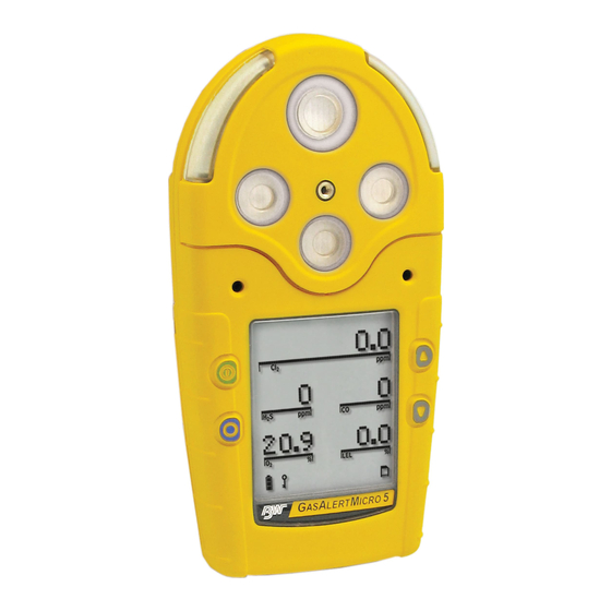
Maintenance. • Batteries: three replaceable alkaline cells or one To become oriented with the features and functions of the rechargeable battery pack with the GasAlertMicro 5 detector, refer to the following figures and tables: Battery Charger • Figure 1 and Table 3 describes the detector’s •... - Page 13 GasAlertMicro 5 and GasAlertMicro 5 PID Getting Started Table 3. GasAlertMicro 5 and GasAlertMicro 5 PID Detector Item Description Visual alarm bars (LED) Sensors Audible alarm Pushbuttons Liquid crystal display (LCD) Battery pack Alligator clip Figure 1. GasAlertMicro 5 and GasAlert Micro 5 PID Detector...
- Page 14 GasAlertMicro 5 and GasAlertMicro 5 PID User Manual Table 4. Display Elements Item Description Alarm condition Automatically span sensor Gas cylinder Gas identifier bars Battery life indicator Pass code lock Data transmission Clock Stealth mode Optional pump indicator Optional datalogger card indicator...
- Page 15 GasAlertMicro 5 and GasAlertMicro 5 PID Getting Started Table 5. Pushbuttons Pushbutton Description • To turn on the detector press A. • To turn off the detector, press and hold A until the countdown is complete (from normal operation only).
-
Page 16: Activating The Detector
GasAlertMicro 5 and GasAlertMicro 5 PID User Manual Activating the Detector Attach all of the accessories prior to activating the detector (e.g., pump module, sampling probe, hose, etc.). For illustrations and procedures, refer to Attaching the Accessories. To activate the detector, press A in a normal atmosphere Replace the batteries and reactivate the detector. - Page 17 GasAlertMicro 5 and GasAlertMicro 5 PID Activating the Detector The version and serial number of the detector Note displays. If there is a problem with the MMC/SD, Datalogger disabled displays. The detector then automatically continues with the self-test. If the card requires formatting, the following screen displays as the card is automatically formatted.
- Page 18 GasAlertMicro 5 and GasAlertMicro 5 PID User Manual If correction factors are set in the user options, the Self-test Successful: If successful, the following screen LEL or PID (custom) correction factors display. displays. Self-test Unsuccessful: If a sensor fails the self-test, a The TWA, STEL, low, and high alarm setpoints warning displays indicating which sensor(s) has failed.
- Page 19 GasAlertMicro 5 and GasAlertMicro 5 PID Activating the Detector When the following screen displays, block the pump inlet. If the pump inlet is not blocked within 10 seconds or the pump test fails, the following screens display. Pump Test (Optional) If the pump module is attached to the detector, the following screens display.
- Page 20 GasAlertMicro 5 and GasAlertMicro 5 PID User Manual If the pump test is successful, the following screen 10. Lastly, the number of days remaining before displays and the self-test continues. calibration is due displays for all sensors. Unless disabled in user options, the oxygen (O If any sensor is past due for calibration, the name of sensor is calibrated automatically.
- Page 21 GasAlertMicro 5 and GasAlertMicro 5 PID Activating the Detector The self-test is now complete. If Due-lock is disabled, the Force Calibration Is Enabled detector enters normal operation. If Force cal is enabled in the user options menu, calibration is mandatory before the detector enters normal operation.
- Page 22 GasAlertMicro 5 and GasAlertMicro 5 PID User Manual Daily Bump Note If the bump test is not performed, the detector If the Bump Daily (Bmp daily) option is enabled from deactivates. Tech Mode, the following bump test mandatory screen displays.
-
Page 23: Self-Test Pass
GasAlertMicro 5 and GasAlertMicro 5 PID Activating the Detector Self-Test Pass Battery Test If the detector passes the self-test, it enters normal operation The batteries are tested when the detector is activated and displaying the ambient gas readings. continuously thereafter. The battery power icon displays continually during normal operation. -
Page 24: Deactivating The Detector
GasAlertMicro 5 and GasAlertMicro 5 PID User Manual The available user options are as follows: Deactivating the Detector To deactivate the detector, press and hold A while it beeps Exit; and flashes to the corresponding countdown. Options: backlight, confidence beep, due-lock, latch, passcode, safe, and fast pump;... -
Page 25: Exit User Options Menu
GasAlertMicro 5 and GasAlertMicro 5 PID User Options Menu To enter the user options menu, press and hold G and H Note simultaneously as the detector beeps and flashes to the If no pushbuttons are pressed for 20 seconds, the corresponding countdown. - Page 26 GasAlertMicro 5 and GasAlertMicro 5 PID User Manual Backlight Due-Lock The backlight (Backlght) option is used If Due-lock is enabled and a sensor is to enable the LCD backlight to activate overdue for calibration upon start-up, the automatically in low-light conditions.
- Page 27 GasAlertMicro 5 and GasAlertMicro 5 PID User Options Menu Passcode Protect Safe Display The passcode option is used to prevent When enabled, the safe option confirms unauthorized access to the user options that normal ambient conditions prevail menu, the calibration function, and to and there are no gas hazards present.
-
Page 28: Sensor Configuration
GasAlertMicro 5 and GasAlertMicro 5 PID User Manual From the option menu screen, scroll to Sensors and Sensor Configuration press C to access the following screen. The Sensor options provide access to additional options and functions that are available for each sensor. - Page 29 GasAlertMicro 5 and GasAlertMicro 5 PID User Options Menu If disabled, the readings for the senor do not display when in Sensor Enable/Disable normal operation. a Warning If a sensor is enabled but it is not installed in the detector, Disabling an installed sensor configures the FAIL displays above the gas bar of the missing sensor.
- Page 30 GasAlertMicro 5 and GasAlertMicro 5 PID User Manual Span Gas Value STEL Period The Span gas option is used to The STEL period option is available for increase/decrease the gas concentration every toxic sensor. level for calibration (it must match the After selecting the desired sensor, press value on the gas cylinder).
- Page 31 GasAlertMicro 5 and GasAlertMicro 5 PID User Options Menu TWA Method Resolution The TWA method is used to select either This option is used to display the gas the Occupational Safety and Health measurement using Regular or Extra Administration (OSHA) or the American resolution.
- Page 32 GasAlertMicro 5 and GasAlertMicro 5 PID User Manual (LEL Sensors Only) % Vol CH LEL Sensor This option is used to enter compensation If the % vol is enabled, any currently factors for hydrocarbons other than enabled correction factor is ignored and methane.
- Page 33 GasAlertMicro 5 and GasAlertMicro 5 PID User Options Menu PID Sensor Automatic Oxygen (O ) Calibration This option is used to enter compensation When the Autocal option is enabled, it factors for selected gas types. The factor forces the detector to automatically...
-
Page 34: Logger Option
GasAlertMicro 5 and GasAlertMicro 5 PID User Manual If C is not pressed within 5 seconds, the following screen Logger Option displays. This option is used to set how often the detector records a datalog sample (once every 1 to 127 seconds). -
Page 35: Language Selection
GasAlertMicro 5 and GasAlertMicro 5 PID User Options Menu The screen displays showing the month highlighted indicating Language Selection it is selected to set. The detector is shipped with English as the default language. The available languages to select from are as follows: •... -
Page 36: Tech Mode
GasAlertMicro 5 and GasAlertMicro 5 PID User Manual In the following order, press and continue to hold each button until Tech mode displays. Press and hold H with right index finger. Press and hold G with right middle finger. Press and hold C with left thumb. - Page 37 GasAlertMicro 5 and GasAlertMicro 5 PID User Options Menu Sensors A corresponding list of toxic sensors a Caution displays. A checkbox displays beside the current toxic sensor. Physically change the sensor prior to entering Tech Mode to reconfigure the sensor type.
- Page 38 GasAlertMicro 5 and GasAlertMicro 5 PID User Manual (Optional Accessory) Pump Exit the user options menu. The detector automatically launches the pump test a Warning before returning to normal operating Use only the pump that is provided with the detector. Do mode.
- Page 39 GasAlertMicro 5 and GasAlertMicro 5 PID User Options Menu Force Calibration If No is selected, the following screen displays and the detector exits the The Force cal option is used to force the initialize option. detector to enter calibration if a sensor is overdue upon start-up.
- Page 40 GasAlertMicro 5 and GasAlertMicro 5 PID User Manual Stealth Mode IR Stealth Mode (Optional) Note This is an optional feature and must be factory ordered. The Stealth and IR Stlth options cannot be enabled simultaneously. Note The Stealth and IR Stlth options cannot be The Stealth option is used to disable the enabled simultaneously.
-
Page 41: Alarms
GasAlertMicro 5 and GasAlertMicro 5 PID Alarms If more than one type or level of alarm exists simultaneously, Alarms a multi-gas alarm will result. The following table describes the detector alarms and To change the factory-set alarm setpoints, refer to corresponding screens. - Page 42 GasAlertMicro 5 and GasAlertMicro 5 PID User Manual Table 6. Alarms (cont.) Alarms Display Alarms Display Multi-Gas Alarm: Over Range Alarm: (Over Level Exposure) • Alternating low and high alarm beep and flash • Fast beep and flash • L and target gas bars flash •...
- Page 43 GasAlertMicro 5 and GasAlertMicro 5 PID Alarms Table 6. Alarms (cont.) Alarms Display Alarms Display Confidence Beep: MMC Fail Alarm: • Two fast beeps every • One beep every 5 seconds 10 seconds • S flashes Alarms Displays Pump Alarm: •...
-
Page 44: Gas Exposures Computed
GasAlertMicro 5 and GasAlertMicro 5 PID User Manual Viewing Gas Exposures Gas Exposures Computed Press and hold C until the a Warning MAX gas exposures screen To avoid possible personal injury, do not displays. deactivate the detector during a work shift. -
Page 45: Clearing Gas Exposures
GasAlertMicro 5 and GasAlertMicro 5 PID Alarms Clearing Gas Exposures Table 8. Gas Alarm Setpoints The exposures automatically clear after 5 minutes of the Alarm Condition detector being deactivated. Low alarm Toxics and combustibles: Ambient gas level above low alarm setpoint. -
Page 46: Resetting Gas Alarm Setpoints
GasAlertMicro 5 and GasAlertMicro 5 PID User Manual Resetting Gas Alarm Setpoints Note Standard factory alarm setpoints vary by region. The following table lists the factory alarm setpoints according to the Occupational Safety and Health Association (OSHA) settings. Table 9. OSHA Sample Factory Alarm Setpoints... -
Page 47: Stopping A Gas Alarm
GasAlertMicro 5 and GasAlertMicro 5 PID Alarms To change the factory-set alarm setpoints, refer to Calibration and Setting Alarm Setpoints. Note To disable an alarm, set the alarm setpoint to 0 (zero). Pump Alarm Stopping a Gas Alarm The external pump draws air over the sensors continually. If... -
Page 48: Low Battery Alarm
LCD deactivates and the detector exits normal • CG-Q58-4 and CG-Q34-4 calibration gas (4-gas mix) operation. are available from BW Technologies. See the section, To replace or charge the batteries, refer to Replacement Parts and Accessories. Replacing/Charging the... -
Page 49: Diagnostics Protection
GasAlertMicro 5 and GasAlertMicro 5 PID Calibration and Setting Alarm Setpoints • • Calibration accuracy is never better than the calibration If the Auto cal option is enabled, the oxygen (O gas accuracy. BW Technologies recommends a sensor calibrates automatically every time the detector premium-grade calibration gas. -
Page 50: Applying Gas To The Sensors
GasAlertMicro 5 and GasAlertMicro 5 PID User Manual In auto span, if target gas is not detected or does not meet expected values, a message displays that the detector is exiting calibration mode. The detector retains the previous set values. - Page 51 GasAlertMicro 5 and GasAlertMicro 5 PID Calibration and Setting Alarm Setpoints Start Calibration Auto Zero and Oxygen (O ) Sensor Calibration Note flashes while the detector automatically zeroes the toxic and combustible sensors, and Verify that the calibration gas being used matches calibrates the O sensor.
- Page 52 GasAlertMicro 5 and GasAlertMicro 5 PID User Manual The passcode must be entered to proceed. If required, refer Auto Span Passcode Protect in User Options menu. After auto zero and the correct passcode is entered (if required), the following three screens display.
- Page 53 A generator must be used for O and ClO sensors. • : BW recommends that a Tedlar bag be used as a buffer between the generator and the detector (while using the calibration cap) to regulate the flow rate to ensure accurate readings.
- Page 54 GasAlertMicro 5 and GasAlertMicro 5 PID User Manual Insufficient Level: If a sensor does not attain a sufficient Select Sensor level of expected gas, it is cleared from the LCD and is not If C is pressed to select Sensor, the following screen spanned.
- Page 55 GasAlertMicro 5 and GasAlertMicro 5 PID Calibration and Setting Alarm Setpoints If all of the sensors have successfully spanned, the Skip Calibration following screen displays prior to continuing with If A is pressed, proceed to step #6. the calibration process.
- Page 56 GasAlertMicro 5 and GasAlertMicro 5 PID User Manual Failed Span If a sensor fails the span, the following error message displays. Press A to exit and then restart calibration in an atmosphere that is clear of the targeted gases. If the span fails a second time, restart the detector to test the sensors.
- Page 57 GasAlertMicro 5 and GasAlertMicro 5 PID Calibration and Setting Alarm Setpoints If the detector fails to span the sensors, confirm the following: Did Not Reach Target Span If the span did not reach the target span as set in the user •...
- Page 58 GasAlertMicro 5 and GasAlertMicro 5 PID User Manual The following screen displays. Large Span If the span adjustment is unusually large (more than 15%), the following screens display. Press C to set the calibration due dates. The following screens display.
- Page 59 GasAlertMicro 5 and GasAlertMicro 5 PID Calibration and Setting Alarm Setpoints The calibration due dates are set in the following To change the calibration due date (1-365 days), order: press H or G until the new value displays. Press C within 5 seconds to confirm.
- Page 60 GasAlertMicro 5 and GasAlertMicro 5 PID User Manual Repeat step #7 to set the calibration due date for When setting alarm setpoints, if the new setpoint is not the remaining sensors. confirmed within 5 seconds by pressing C, the following screen displays.
- Page 61 GasAlertMicro 5 and GasAlertMicro 5 PID Calibration and Setting Alarm Setpoints Setting the TWA Alarm Setpoint Setting the Low Alarm Setpoint The current TWA alarm setpoint displays for the selected The current low alarm setpoint displays for the selected sensor (if applicable).
- Page 62 GasAlertMicro 5 and GasAlertMicro 5 PID User Manual Setting the Remaining Alarm Setpoints Repeat steps #10-13 to set alarm setpoints for the remaining sensors. The audible alarm beeps four times when the alarm setpoint function is complete. When the due dates have been set for all required sensors, the detector emits two quick The detector then returns to normal operation.
-
Page 63: Attaching The Accessories
Description Installing the Pump Module Motorized pump module The BW motorized pump module is an optional accessory for Sensor filter the detector. The pump module is designed to be used with the sample probe to test for gases in confined spaces. -
Page 64: Attaching The Sample Probe
GasAlertMicro 5 and GasAlertMicro 5 PID User Manual Attaching the Sample Probe Table 13. Attaching the Sample Probe The sample probe is used to safely test for gas in confined Item Description spaces before entering. Motorized pump module Connector Sample probe Sample probe 10 in. -
Page 65: Datalogger
GasAlertMicro 5 and GasAlertMicro 5 PID Datalogger The following information is recorded in a datalog: a Warning If the length of the tubing is 50 ft. or longer, the • Date and time Fast Pump option must be enabled prior to sampling. -
Page 66: Multimediacard (Mmc) Compatibility
GasAlertMicro 5 and GasAlertMicro 5 PID User Manual MultiMediaCard (MMC) Compatibility An Infineon 32 MB MMC Flash Memory card is supplied with the detector. a Caution To ensure the Intrinsic Safety rating of the detector, use only the 32 MB Infineon MMC. -
Page 67: Mmc/Sd Troubleshooting
GasAlertMicro 5 and GasAlertMicro 5 PID MMC/SD Troubleshooting MMC/SD Troubleshooting The MMC or secure digital (SD) card is not required for operation in detectors equipped with datalogging. However, the following two screens display if the card is not inserted. a Warning Only erased data files can be restored using the detector. -
Page 68: Reformatting The Mmc
GasAlertMicro 5 and GasAlertMicro 5 PID User Manual If the detector successfully restores the log file, the After verifying that the log file has been restored, following screen displays and the start-up tests re-insert the MMC into the detector. continue. -
Page 69: Import Datalogs To Fleetmanager
GasAlertMicro 5 and GasAlertMicro 5 PID Import Datalogs to FleetManager Press G to format the MMC. The following screen Using MicroDock II to Import to FleetManager displays. Note If the detector is used with the MicroDock II Automatic Test and Calibration Station to import datalogs to FleetManager, refer to the MicroDock II User Manual for complete instructions. -
Page 70: View Datalog Files In Spreadsheets
GasAlertMicro 5 and GasAlertMicro 5 PID User Manual From the computer desktop, click FleetManager. A View Datalog Files in Spreadsheets popup displays. Select one of the following: The datalog files can be loaded from the MMC/SD into most • spreadsheet applications using a card reader. Compatible... - Page 71 GasAlertMicro 5 and GasAlertMicro 5 PID View Datalog Files in Spreadsheets Example of a Datalog Spreadsheet When datalog information is imported into most spreadsheet software, it appears similar to the example below. Note: Not all columns are included in this example. Additional Toxic TWA and Toxic STEL display on a normal spreadsheet.
- Page 72 GasAlertMicro 5 and GasAlertMicro 5 PID User Manual Table 16. Datalog Status Codes Status Codes ⎯ Normal operation Backlight is on Low alarm STEL and high alarm (dual alarms) Alarm setpoint 1 (low alarm) High alarm TWA and STEL alarm (dual alarms)
- Page 73 GasAlertMicro 5 and GasAlertMicro 5 PID View Datalog Files in Spreadsheets Table 17. Datalog Gas and Correction Factor Sensor Codes Gas Sensor Codes No sensor S COSH CO COSH Correction Factor Codes for PID (if applicable) Acetaldhyde Acetone Ammonia Benzene...
-
Page 74: Maintenance
GasAlertMicro 5 and GasAlertMicro 5 PID User Manual ⇒ Use only batteries that are recommended by BW Maintenance Technologies to prevent personal injury and/or property damage. To maintain the detector in good operating condition, perform the following basic maintenance as required. -
Page 75: Replacing A Sensor Or Sensor Filter
GasAlertMicro 5 and GasAlertMicro 5 PID Maintenance To replace the alkaline batteries, refer to Table 18, Figure 7, Open the latch on the bottom of the detector. and the following procedures. Remove the battery pack by lifting the bottom of the pack away from the detector. - Page 76 GasAlertMicro 5 and GasAlertMicro 5 PID User Manual To replace a sensor or sensor filter, refer to Figure 8, Table 19. Replacing a Sensor or Sensor Filter Table 19, and the following procedures. Item Description Sensor cover Sensor filter Sensors...
-
Page 77: Photoionization Detector (Pid)
Clean or Replace the Lamp The PID lamp must be cleaned on a regular basis. Use only the cleaning kit that is supplied by BW Technologies. To clean the PID lamp, refer to the illustrations and procedures that are provided with the PID Lamp Cleaning Kit. - Page 78 GasAlertMicro 5 and GasAlertMicro 5 PID User Manual Replace the Lamp Replace the Electrode Stack Replace the lamp when it falls below the acceptable level. Replace the electrode stack when it is contaminated. To Possible indicators that the lamp requires replacement are...
-
Page 79: Troubleshooting
GasAlertMicro 5 and GasAlertMicro 5 PID Troubleshooting If the problem persists, contact Technologies. Troubleshooting If a problem occurs, refer to the solutions provided in Table 21. Table 21. Troubleshooting Tips Problem Possible Cause Solution The detector does activate. No batteries... - Page 80 GasAlertMicro 5 and GasAlertMicro 5 PID User Manual Table 21. Troubleshooting Tips (cont.) Problem Possible Cause Solution The MMC/SD is not inserted Insert the MMC/SD card. Refer to Inserting the MMC/SD Card. The MMC/SD card that is inserted in the...
- Page 81 GasAlertMicro 5 and GasAlertMicro 5 PID Troubleshooting Table 21. Troubleshooting Tips (cont.) Problem Possible Casue Solution The detector displays a clock error General fault Reactivate the detector. If the message message using last recorded time. does not display, reset the clock in user options.
- Page 82 GasAlertMicro 5 and GasAlertMicro 5 PID User Manual Table 21. Troubleshooting Tips (cont.) Problem Possible Cause Solution Detector does not enter alarm mode. Alarm setpoint(s) are set incorrectly Reset alarm setpoints. Refer to Calibration and Setting Alarm Setpoints. Alarm setpoint(s) set to zero Reset alarm setpoints.
-
Page 83: Replacement Parts And Accessories
GasAlertMicro 5 and GasAlertMicro 5 PID Replacement Parts and Accessories Model No. Description Replacement Parts and Accessories SR-G04 sensor a Warning D4-RHM04 TwinTox CO/H S sensor To avoid personal injury and/or damage to the SR-Q07 PID sensor detector, use only the specified replacement RL-PID10.6... - Page 84 GasAlertMicro 5 and GasAlertMicro 5 PID User Manual Model No. Description Model No. Description Calibration gas, H S 25 ppm M5-BAT02 Alkaline battery pack G0042-H25 (58 l) M5-CO1* GasAlertMicro 5 battery charger Calibration gas, CO 200 ppm CG2-M-200-103 GasAlertMicro 5 battery charger...
-
Page 85: Specifications
GasAlertMicro 5 and GasAlertMicro 5 PID Specifications : 0 – 50.0 ppm (0.1 ppm increments) Specifications : 0 – 100 ppm (1 ppm increments) : 0 – 99.9 ppm (0.1 ppm increments) Instrument dimensions: 14.5 x 7.4 x 3.8 cm HCN: 0 –... - Page 86 GasAlertMicro 5 and GasAlertMicro 5 PID User Manual User field options: Confidence beep, latching low and high Approvals alarms, pass code protection, enable/disable safe display mode, Approved by CSA to both U.S. and Canadian Standards enable/disable fast pump, combustible sensor measurement, Approved: Class l, Division 1, Group A, B, C, and D;...
- Page 87 GasAlertMicro 5 and GasAlertMicro 5 PID Specifications GasAlertMicro 5 and GasLaertMIcro 5 PID with General Specifications for Datalogger Units User Downloadable Datalogger Media type: MultiMediaCard (MMC) Operation: Requires no user intervention (automatic) Size: 32 MB (Infineon MMC only) Indicators: Icon advises datalogger is operating normally, Storage: 500,000 lines of data available;...
-
Page 88: Appendix A Pid Correction Library
GasAlertMicro 5 and GasAlertMicro 5 PID User Manual Appendix A PID Correction Factor (CF) Library Table 23. PID Corrections Factor (CF) Library Correction Factor Value Gas # Gas Type LCD Gas Type Abrreviation (CF values subject to change) No PID correction factor... - Page 89 GasAlertMicro 5 and GasAlertMicro 5 PID Appendix A PID Correction Factor (CF) Library Table 23. PID Correction Factors (CF) Library (cont.) Correction Factor Value Gas # Gas Type LCD Gas Type Abrreviation (CF values subject to change) Naptha Naptha d’1.0’...
Need help?
Do you have a question about the GasAlertMicro 5 and is the answer not in the manual?
Questions and answers