Advertisement
Quick Links
Advertisement

Related Manuals for Wistron NeWeb D54A1


Summary of Contents for Wistron NeWeb D54A1
- Page 1 Connected Cooler Radio Quick Start Guide...
-
Page 2: Table Of Contents
Table of Contents 1. GETTING STARTED ....................5 1.1 U ..................5 NPACKING NFORMATION 1.2 I ...................... 5 NTRODUCTION 2. PORTS AND LED INDICATORS ................6 2.1 P ......................... 6 ORTS 2.2 LED I ....................7 NDICATORS 3. INSTALLATION ..................... 8 4. - Page 3 Description: Connected Cooler Radio USA and North America version Radio-related Software Version: D54A1_v00.01 Supplied Accessories and Components: NA We, Wistron NeWeb Corporation, declare under our sole responsibility that the product described above is in conformity with the relevant Union harmonization legislations:...
- Page 4 Signed for and on behalf of: Wistron NeWeb Corporation Place: 20 Park Avenue II, Hsinchu Science Park, Hsinchu 308, Taiwan, R.O.C, Date: January 4, 2017 Name: Brian Lin; function: Technical Manager; signature:...
-
Page 5: Getting Started
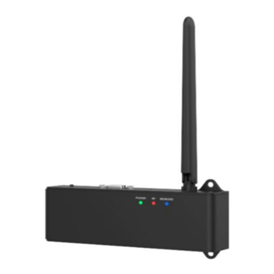
1. Getting Started 1.1 Unpacking Information The Connected Cooler Radio (CCR) Battery notice card Battery Notice Card 1.2 Introduction The Connected Cooler Radio (CCR) works with sensors installed in coolers to deliver cooler information to Cloud servers for better monitoring and management. -
Page 6: Ports And Led Indicators
2. Ports and LED Indicators 2.1 Ports Port Description Power Power supply connection Self-test button The button for activating the self-test process Sensor port Connects to sensors installed in the cooler Engineering For engineering uses only Antenna connection... -
Page 7: Led Indicators
2.2 LED Indicators Power Sensors Indication Description All self-tests passed, and the battery is full. Steady green Power All self-tests passed, and the battery is Blinking green charging No power connection Other failures; for example, SIM card, Steady red battery, or Wi-Fi functions Unsuccessful antenna connection Blinking red The self-test mode is running. -
Page 8: Installation
3. Installation 1. Place the CCR in the specified location (for example wall) and affix the screws. Screw Screw Screw Screw type M4 2. Attach the antenna to the antenna port of the CCR. Antenna 3. Connect the power port to the power supply. Power connection... - Page 9 4. Connect the Sensor port to the sensors. Sensors 5. Press the Self-test button. The system begins testing the CCR and the sensors attached to the CCR. Self-test button 6. The system will be ready for use when the Power LED returns to steady green, indicating the system functions normally.
-
Page 10: Specifications
4. Specifications Specifications Standards Wi-Fi: IEEE 802.11b/g/n (2.4 GHz) LTE CAT1: B2/4/5/12; 3G: B2/5 Max. power Mobile for each Max. Antenna frequency Power Power peak Gain class Antenna Typy (dBm) (dBi) Antenna Gain LTE B2 LTE B4 24.5 Band(s) LTE B5 LTE B12 24.5 FDD II... - Page 11 WLAN 11b/g/n WiFi TX Max Power(dBm) 17.9 Antenna peak Gain (dBi) internal PCB antenna Antenna type Max Power(dBm) Antenna peak Gain (dBi) internal PCB antenna Antenna type Regions and countries applicable Connection USIM 3FF, VGA for sensor(optional) interfaces Power input 12 V DC/ 1 A (powered by UL Listed power source.) Backup battery: 3.7 V >...
- Page 12 5. Instruction Instruction CAUTION Only authorized service providers shall replace battery. Do not disassemble or open crush, bend or deform, puncture or shred Do not modify or remanufacture, attempt to insert foreign objects into the battery, immerse or expose to water or other liquids, expose to fire, explosion or other hazard.
- Page 13 Specific Absorption Rate information This mobile device meets the government’s requirements for exposure to radio waves. Your mobile device is a radio transmitter and receiver. The exposure standard for mobile devices employs a unit of measurement known as the Specific Absorption Rate, or SAR. The SAR limit adopted by Europe is 2.0 W/kg averaged over 10 grams of tissue.
- Page 14 FCC Regulations: This device complies with part 15 of the FCC Rules. Operation is subject to the following two conditions: (1) This device may not cause harmful interference, and (2) this device must accept any interference received, including interference that may cause undesired operation.
- Page 15 -Reorient or relocate the receiving antenna. -Increase the separation between the equipment and receiver. -Connect the equipment into an outlet on a circuit different from that to which the receiver is connected. -Consult the dealer or an experienced radio/TV technician for help. Caution: Changes or modifications not expressly approved by the party responsible for compliance could void the user‘s authority to operate the equipment.
- Page 16 ISED Notice This device complies with Innovation, Science and Economic Development Canada license-exempt RSS standard(s). Operation is subject to the following two conditions: (1) this device may not cause interference, and (2) this device must accept any interference, including interference that may cause undesired operation of the device.
- Page 17 Cet appareil numérique de la classe B est conforme à la norme NMB-003 du Canada. ISED RF Exposure Statement This device complies with ISED RSS-102 RF exposure limits set forth for an uncontrolled environment. In order to avoid the possibility of exceeding the ISED RSS-102 RF exposure limits, human proximity to the antenna shall not be less than 20cm (8 inches) during normal operation.
Need help?
Do you have a question about the D54A1 and is the answer not in the manual?
Questions and answers