
Summary of Contents for SCINTEX RG-1
- Page 1 RG-1 Remote Operating Gravity Meter Operation Manual RG-1 Operation Manual p/n 910702 Rev.0...
- Page 2 Rev. Description of Change Date of Issue Initial Release 7775 6/29/2021 RG-1 Operation Manual p/n 910702 Rev.0...
- Page 3 No part of this publication may be reproduced, stored in a retrieval system or transmitted, in any form, or by any means, electronic, mechanical, photo-copying, recording, or otherwise without prior consent from SCINTREX Limited. 910702 Rev.0 ECO 7775 RG-1 Operation Manual p/n 910702 Rev.0...
-
Page 4: Table Of Contents
Powering up the RG-1 ..................2—11 Charging the RG-1 Battery ................2—12 Connecting RG-1 to Laptop Computer ..............2—13 Chapter 3 Operating RG-1 with RGS Software ............3—1 Launching RGS ..................... 3—1 Checking I/O Settings .................... 3—2 Create New Session ....................3—4 Connect to RG-1 .................... - Page 5 Description of the instrument Introduction to the manual and 2. Getting started description of the instrument’s components. 3. Setting up Setup of your RG-1 for a survey. 4.Operation Operating your RG-1 during a survey. How to maintain and troubleshoot your 5. Maintenance RG-1.
-
Page 6: Chapter 1 Instrument Overview
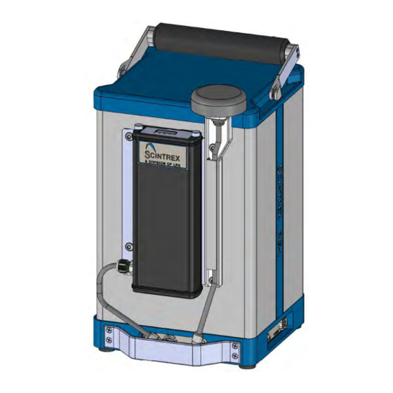
Instrument Overview Chapter 1 Instrument Overview Figure 1-1 The RG-1 Remote Operating Gravity Meter 1—1 RG-1 Operation Manual p/n 910702 Rev.0... - Page 7 The laptop computer is pre-loaded with RGS software that allows user to remotely setup, level, record, and continuously monitor gravity and other signals. When the included battery and GPS antenna are attached to the RG-1 it can be used, together with the laptop as a land gravity meter.
-
Page 8: Chapter 2 Getting Started
Chapter 2 Getting Started Unpacking the Instrument The RG-1 is packed in a padded case (with the battery stored separately and packaged individually to comply with IATA transport safety regulations) to protect the instrument during shipment and transportation to the field. - Page 9 Figure 2-2 Location of the pressure release valve on the transportation case 4. Open the RG-1 transportation case by lifting the lid. 5. Remove the RG-1 from the transportation case by pulling directly upward on the handle and visually inspect for any physical damage that may have occurred during transportation.
-
Page 10: Overview Of The Components
Figure 2-3 ShockWatch monitor Overview of the Components The following picture shows an overhead view of the all the components that are supplied with a standard RG-1 in its transportation case. Figure 2-4 RG-1 Remote Gravity Meter and its components 2—3... - Page 11 Getting Started Figure 2-5 RG-1 Components Figure 2-6 RG-1 Components (cont'd) 2—4 RG-1 Operation Manual p/n 910702 Rev.0...
-
Page 12: Overview Of The Unit
HD SLOT 10-32 3/8 ULTRA WD [330019]. Note: The RG-1 unit is fully operational in this configuration. To proceed please go to ‘Starting up the RG-1’. Continue reading for the installation of accessories that enables RG-1 to be operated in a stand-alone package. -
Page 13: Assembling Rg-1 To Stand-Alone Configuration
Getting Started Assembling RG-1 to Stand-alone Configuration Installing the external battery and GPS assembly enables the RG-1 remote gravity meter to be operated as a stand-alone land gravity meter. Note: To operate the meter and record data, RG-1 needs to be connected... -
Page 14: Installing Gps Assembly
HEX 10-32 5/8 FLANGED [280009] and SCREWDRIVER HEX 1/8" 263 [540085] from Tool kit. Engage Battery connector. Figure 2-9 RG-1 External Battery Fully Installed (unit: cm) Installing GPS Assembly Remove the 2x SCREWS BH HEX 10-32 5/8 FLANGED [280009] from the right side of the Battery Assembly, slide them under GPS ANTENNA ASSY [910568] cable, and use them to attach the GPS Antenna Assy to the Battery Assembly plate. - Page 15 Getting Started Figure 2-10 RG-1 Power and GPS Connector Engaged Figure 2-11 Installing Connectors Cover 2—8 RG-1 Operation Manual p/n 910702 Rev.0...
- Page 16 Getting Started Figure 2-12 RG-1 GPS Assembly Fully Installed (unit: cm) 2—9 RG-1 Operation Manual p/n 910702 Rev.0...
-
Page 17: Fully Assembled Rg-1 Unit
Getting Started Fully Assembled RG-1 Unit The following picture shows a fully assembled RG-1 Unit in the stand-alone configuration. Figure 2-13 Fully Assembled RG-1 Unit 2—10 RG-1 Operation Manual p/n 910702 Rev.0... -
Page 18: Starting Up The Rg-1
Getting Started Starting up the RG-1 Starting-up the RG-1 for the first time, or after it has been turned off for more than 24 hours, requires the following steps and waiting periods. Powering up the RG-1: Please refer to the section entitled: Powering up the RG-1 below. -
Page 19: Charging The Rg-1 Battery
Charging takes approximately 4 hours if the battery has been fully discharged. Charging the RG-1 Battery In addition to being charged in-situ in the RG-1, battery can also be charged with the Smart Battery Charger [400209], To charge battery, open Battery Assembly as shown (no need to disconnect from RG-1 unit). -
Page 20: Connecting Rg-1 To Laptop Computer
Getting Started Connecting RG-1 to Laptop Computer The RG-1 is connected to the laptop computer via the supplied RS232 cable [910532]. Figure 2-17 RS232 Cable connected to RS232 Port on RG-1 Figure 2-18 RS232 Cable connected to Laptop 2—13 RG-1 Operation Manual p/n 910702 Rev.0... - Page 21 Getting Started Figure 2-19 RG-1 Connected to Laptop Computer 2—14 RG-1 Operation Manual p/n 910702 Rev.0...
-
Page 22: Launching Rgs
Double click ‘RGS’ shortcut on the desktop of the supplied laptop computer. Figure 3-1 RGS Main Screen Note: The layout of the main screen can be re-organized by moving and resizing each individual window. 3—1 RG-1 Operation Manual p/n 910702 Rev.0... -
Page 23: Checking I/O Settings
Operating RG-1 with RGS Software Checking I/O Settings Open Windows Device Manger and confirm the COM port number that RG-1 occupies. Figure 3-2 Device Manager: COM Ports Back to RGS, go to Edit\Settings. Under I\O tab, click ‘Probe Setup’ button. - Page 24 Operating RG-1 with RGS Software Make sure port is set to the COM number that the RG-1 is currently using. Make sure Baud rate is set to 38400/8-N-1. Figure 3-4 RGS Serial Port Settings. 3—3 RG-1 Operation Manual p/n 910702 Rev.0...
-
Page 25: Create New Session
Figure 3-5 RGS Create New Session Click No and select existing settings (.ini) file in the next screen. Figure 3-6 RGS Load Existing .ini File Click No and select existing meter (.sys) file in the next screen. 3—4 RG-1 Operation Manual p/n 910702 Rev.0... - Page 26 Operating RG-1 with RGS Software Figure 3-7 RGS Load Existing .sys File Click Yes to confirm. Figure 3-8 RGS Confirm New Session 3—5 RG-1 Operation Manual p/n 910702 Rev.0...
-
Page 27: Connect To Rg-1
Figure 3-10 Communication Menu: Connect Button After a few seconds, upon hearing a beeping sound, you will notice more options enabled in the toolbar. RGS software is now connected to RG-1 and ready to operate. Figure 3-11 More Toolbar Icons Enabled after Successful Connection 3—6... -
Page 28: Level And Measure Gravity
After successful connection, click Level and Gravity icon in the toolbar. Figure 3-12 Toolbar: ‘Level and Gravity’Icon After a beeping sound, RG-1 will start self-leveling. The Status section of RGS Data window will display the current leveling status. Figure 3-13 RGS Data Window: Leveling Note: Leveling will alternate between X and Y axis. -
Page 29: Record Data
When data is being recorded, Status box in RGS Data window will glow green. Figure 3-16 RGS Data Window: Recording Note: Name and directory of recorded data file is specified under Edit Menu \ Settings \ I/O tab. 3—8 RG-1 Operation Manual p/n 910702 Rev.0... -
Page 30: Recalling Your Data
Data Lookup window will show up, with all previous data in the current session. Figure 3-18 Data Lookup Window Note: All previously measured data will show up in Data Lookup window, no matter if they were recorded or not. 3—9 RG-1 Operation Manual p/n 910702 Rev.0... -
Page 31: Putting The Rg-1 Into/Out Of Standby Mode
Operating RG-1 with RGS Software Putting the RG-1 into/out of Standby Mode The RG-1 can be put into standby mode when meter is being moved. It reduces the settling time at the next station by stabilizing the electronics during transport. In this mode the gravity reading is fixed to a default value. - Page 32 Operating RG-1 with RGS Software Viewing and Changing the Calibration Parameters When RGS is disconnected from the RG-1 meter, go to Edit menu and click Settings. Choose Calibration tab. Figure 3-20 Settings Menu: Calibration Note: The Calibration tab is concerned with the current calibrations of the remote gravity meter.
-
Page 33: Performing Tilt Calibration Test
The recommended setting is ±200 for X and Y, which should normally be adequate. When these tests are selected, data is automatically recorded to the default log files set in the System Settings dialog I/O tab page. Figure 3-22 Settings Menu: Tilt Calibration Test 3—12 RG-1 Operation Manual p/n 910702 Rev.0... -
Page 34: Tilt Xy Calibration Test
The meter will then self-level to (0, 0), (-X, 0), (+X, 0), (-Y, 0), (+Y, 0) and (0, 0) positions sequentially. After leveling to each position, gravity is recorded for one minute. Figure 3-24 RGS Mains Screen during a Tilt Calibration Test 3—13 RG-1 Operation Manual p/n 910702 Rev.0... - Page 35 The next screens present the calculated offset and sensitivity values respectively. The user can choose to save either just the offsets, or just the sensitivities, or both. Figure 3-27 Accepting Tilt Calibration Test Results 3—14 RG-1 Operation Manual p/n 910702 Rev.0...
-
Page 36: Tilt X Calibration Test
Tilt Y Calibration Test Tilt Y Calibration Test will have the meter self-level to (0, 0), (0,− ), (0, -Y), (0,+ ), (0, +Y), (0, 0) and only re-calculate sensitivity and offset values for Y. 3—15 RG-1 Operation Manual p/n 910702 Rev.0... -
Page 37: Chapter 4 Maintenance And Troubleshooting
Important: Care must be exercised in handling your RG-1 Gravity Meter. Excessive shocks and vibrations should be avoided. Even though your RG-1 is a very reliable instrument, there can be circumstances where problems may occur. The following table lists some of these problems and their attempted solution. -
Page 38: Chapter 5 Reference Information
Reference Chapter 5 Reference Information RG-1 Technical Specifications Laptop computer and RG-1 specifications are subject to change without notice Sensor Type Fused quartz using electrostatic feedback Reading Resolution 1 microGal Self-Leveling Range ± 45 Degrees Standard Deviation <5 microGal Operating Range... -
Page 39: Integrating Rg-1 To Your Platform
Reference Integrating RG-1 to Your Platform Mounting Holes 5 mounting holes are available at the bottom plate of RG-1 unit. They can be used to mount RG-1 unit to your platform. Figure 5-1 RG-1 Mounting Holes (unit: cm) Mounting Plate If the bottom plate mounting holes are inaccessible from your platform, the supplied mounting plate [910175] can be installed to provide mounting option outside RG-1’s... - Page 40 Reference Figure 5-2 Installing Mounting Plate to RG-1 Figure 5-3 RG-1 Unit with Mounting Plate Installed (unit: cm) 5—3 RG-1 Operation Manual p/n 910702 Rev.0...
-
Page 41: Extended Plate Assembly
Reference Extended Plate Assembly In situations where RG-1 unit needs to be placed on a standard tripod [126370138], the Extended Plate Assembly [910410] needs to be installed. To assemble RG-1 unit with Extended Plate Assembly use screwdriver with #3 Philips bit from Tool Kit [910026] and 5x SCREWS FH PHIL 1/4-20 1 BLACK [280015] from Spare Parts Kit [910422]. - Page 42 Reference Figure 5-6 RG-1 Unit with Extended Plate Assembly, Placed on a Tripod 5—5 RG-1 Operation Manual p/n 910702 Rev.0...
-
Page 43: Location Of The Rg-1 Sensor
Reference Location of the RG-1 Sensor The following picture shows the location of the RG-1 sensor. Figure 5-6 The RG-1 sensor location 5—6 RG-1 Operation Manual p/n 910702 Rev.0... -
Page 44: Instrument Parts List
Battery Storage 910421 Flash Drive with Documents 910407 RG-1 Transportation Case 910016 RG-1 Optional Accessories Item Description Part Number Meter Tripod 126370138 Smart Battery for RG-1 0221029RG 12V External Power Supply Cable 128370060 5—7 RG-1 Operation Manual p/n 910702 Rev.0... -
Page 45: Warranty
Scintrex. Instruments should be shipped to: SCINTREX Limited 222 Snidercroft Road Concord, ON, Canada L4K 2K1 Telephone: +1 905 669 2280 Fax: +1 905 669 6403 5—8 RG-1 Operation Manual p/n 910702 Rev.0...
Need help?
Do you have a question about the RG-1 and is the answer not in the manual?
Questions and answers