Table of Contents
Advertisement
Quick Links
Please use this manual together with the service manual for Model No. [SA-VK72DGCS/GS-S, Order No.
MD0506272C3].
Specifications
n AMPLIFIER SECTION
RMS Output Power: Dolby Digital Mode
Main
70 W per channel (6 Ω), 1 kHz, 10% THD
Surround Ch
55 W per channel (6 Ω), 1 kHz, 10% THD
Center Ch
70 W per channel (6 Ω), 1 kHz, 10% THD
Total RMS Dolby Digital mode power
PMPO output power
n FM/AM TUNER, TERMINALS SECTION
Preset station
Frequency Modulation (FM)
Frequency range
All manuals and user guides at all-guides.com
320 W
4000 W
FM 15 stations
AM 15 stations
87.50 - 108.00 MHz (50 kHz step)
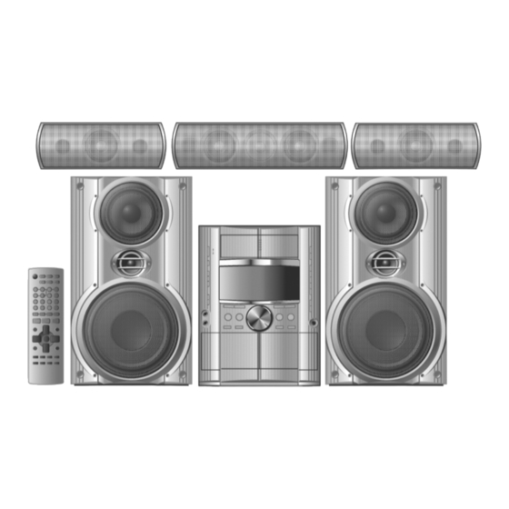
DVD Stereo System
SA-VK725DGC
Colour
(S) .... Silver Type
Sensitivity
S/N 26dB
Antenna terminals
Amplitude Modulation (AM)
Frequency range
AM Sensitivity S/N 20dB at 999 kHz
Audio performance (Amplifier)
Input sensitivity/Input impedance
Aux
Phone jack
Terminal
Mic jack
Sensitivity
© 2005 Matsushita Electric Industrial Co. Ltd.. All
rights
reserved.
distribution is a violation of law.
ORDER NO. MD0507287A3
2.5 µV (IHF)
2.2 µV
75 Ω (unbalanced)
522 - 1629 kHz (9 kHz step)
520 - 1630 kHz (10 kHz step)
560 µV/m
250 mV, 20 kΩ
Stereo, 3.5 mm jack
0.7 mV, 600 Ω
Unauthorized
copying
and
Advertisement
Table of Contents

Related Manuals for Panasonic SA-VK725DGC


Summary of Contents for Panasonic SA-VK725DGC
- Page 1 All manuals and user guides at all-guides.com ORDER NO. MD0507287A3 DVD Stereo System SA-VK725DGC Colour (S) ..Silver Type Please use this manual together with the service manual for Model No. [SA-VK72DGCS/GS-S, Order No. MD0506272C3]. Specifications n AMPLIFIER SECTION Sensitivity 2.5 µV (IHF)
- Page 2 Exif Ver 2.1 JPEG Baseline files Picture resolution: between 160 x 120 and 6144 x 4096 pixels (Sub sampling is 4:2:2 or 4:2:0) MPEG4 data recorded with Panasonic SD multi cameras or DVD video recorders. Conforming to SD VIDEO specifications (ASF standard)/ MPEG4 (Simple Profile) video system/G.726 audio system...
-
Page 3: Table Of Contents
SA-VK725DGC All manuals and user guides at all-guides.com Notes: 1. Specifications are subject to change without notice. Mass and dimensions are approximate. 2. Total harmonic distortion is measured by the digital spectrum analyzer. CONTENTS Page Page 1 Operating Procedures 4.2. (B) Main P.C.B. -
Page 4: Operating Procedures
SA-VK725DGC All manuals and user guides at all-guides.com 1 Operating Procedures... - Page 5 SA-VK725DGC All manuals and user guides at all-guides.com...
-
Page 6: Disc Information
SA-VK725DGC All manuals and user guides at all-guides.com 2 Disc information... -
Page 7: Schematic Diagram (Updating)
SA-VK725DGC All manuals and user guides at all-guides.com 3 Schematic Diagram (Updating) Note: With reference to page 81~87, 89~97 & 104 (section 22) of the original service manual for SA-VK72DGCS/GS-S. Below are the updates. 3.1. (A) DVD Module Circuit SCHEMATIC DIAGRAM - 2... - Page 8 SA-VK725DGC All manuals and user guides at all-guides.com SCHEMATIC DIAGRAM - 3 : +B SIGNAL LINE DVD MODULE CIRCUIT D+3.3V IC8111 C0CBCBD00018 3.3 REGULATOR IC TL8111 D+5V C8111 C8112 IC8111 RX8111 (22K x 2) C8113 470P Cont QR8111 XP0621400L SWITCH QR8571 D+1.2V...
- Page 9 SA-VK725DGC All manuals and user guides at all-guides.com SCHEMATIC DIAGRAM - 4 : MAIN SIGNAL LINE : +B SIGNAL LINE : DVD VIDEO SIGNAL LINE DVD MODULE CIRCUIT FP8101 VGND Y/PY/G Y/PY/G LB8303 J0JBC0000042 VGND CB/PB/B CB/PB/B LB8304 J0JBC0000042 VGND...
- Page 10 SA-VK725DGC All manuals and user guides at all-guides.com SCHEMATIC DIAGRAM - 5 : +B SIGNAL LINE : DVD VIDEO SIGNAL LINE DVD MODULE CIRCUIT EXADR15 EXADR16 EXADR14 XBYTE EXADR13 EXADR12 EXDT15 DQ15/A-1 EXADR11 EXDT7 EXADR10 EXDT14 DQ14 EXADR9 EXDT6 EXADR8...
- Page 11 SA-VK725DGC All manuals and user guides at all-guides.com SCHEMATIC DIAGRAM - 6 : +B SIGNAL LINE DVD MODULE CIRCUIT C8051 MDQ0 MDQ15 DQ15 C8052 VDDQ VSSQ MDQ14 MDQ1 DQ14 MDQ2 DQ13 C8057 RX8012 (82 x 4) VSSQ VDDQ MDQ3A MDQ3...
- Page 12 SA-VK725DGC All manuals and user guides at all-guides.com SCHEMATIC DIAGRAM - 7 : +B SIGNAL LINE DVD MODULE CIRCUIT RX8018 (22 x 2) RX8017 (82 x 4) MDQ18 TRCDATA1 TRCDATA0 VDD33 TRCCLK MDQ28 EXTRGO MDQ19 SDATA MDQ27 SCLOCK MDQ20 EXTRG1...
- Page 13 SA-VK725DGC All manuals and user guides at all-guides.com SCHEMATIC DIAGRAM - 8 : CD-DA SIGNAL LINE : DVD VIDEO SIGNAL LINE : +B SIGNAL LINE : DVD AUDIO SIGNAL LINE DVD MODULE CIRCUIT R8041 LB8011 J0JHC0000045 D+3.3V D+1.2V C8001 C8011...
-
Page 14: B) Main Circuit
SA-VK725DGC All manuals and user guides at all-guides.com 3.2. (B) Main Circuit SCHEMATIC DIAGRAM - 10 : AUX SIGNAL LINE : DVD VIDEO SIGNAL LINE MAIN CIRCUIT : MAIN SIGNAL LINE : VIDEO SIGNAL LINE : +B SIGNAL LINE Q2814... - Page 15 SA-VK725DGC All manuals and user guides at all-guides.com SCHEMATIC DIAGRAM - 11 CD LOADING CIRCUIT (CN1) ON : +B SIGNAL LINE : DVD VIDEO SIGNAL LINE SCHEMATIC DIAGRAM - 26 MAIN CIRCUIT : -B SIGNAL LINE : MAIN SIGNAL LINE...
- Page 16 SA-VK725DGC All manuals and user guides at all-guides.com SCHEMATIC DIAGRAM - 12 TRANSFORMER CIRCUIT (H9502/W9502) : +B SIGNAL LINE : MIC SIGNAL LINE ON SCHEMATIC DIAGRAM - 25 MAIN CIRCUIT : -B SIGNAL LINE : MAIN SIGNAL LINE CN2814 C2108...
- Page 17 SA-VK725DGC All manuals and user guides at all-guides.com SCHEMATIC DIAGRAM - 13 : +B SIGNAL LINE MAIN CIRCUIT : -B SIGNAL LINE : MAIN SIGNAL LINE C2602 C2219 C2306 C2406 C2119 50V4.7 50V2.2 50V2.2 50V4.7 Q2815 Q2816 R2615 R2218 R2306...
- Page 18 SA-VK725DGC All manuals and user guides at all-guides.com SCHEMATIC DIAGRAM - 14 BOTTOM : +B SIGNAL LINE : AUX SIGNAL LINE : FM/AM SIGNAL LINE MAIN CIRCUIT : -B SIGNAL LINE : MAIN SIGNAL LINE : TAPE PLAYBACK SIGNAL LINE...
- Page 19 SA-VK725DGC All manuals and user guides at all-guides.com SCHEMATIC DIAGRAM - 15 : +B SIGNAL LINE : FM/AM SIGNAL LINE MAIN CIRCUIT : -B SIGNAL LINE : MAIN SIGNAL LINE : TAPE PLAYBACK SIGNAL LINE CN2815 Q2911 Q2912 D2914, D2916...
- Page 20 SA-VK725DGC All manuals and user guides at all-guides.com SCHEMATIC DIAGRAM - 16 MAIN CIRCUIT : +B SIGNAL LINE VREF+ BASS LEDCONT PHOTO_1 R2791 PHOTO_2 R2792 DECK2 R2797 KEY1 R2672 KEY2 R2798 KEY3 R2708 C2718 470P R2723 R2086 R2658 C2721 C2719 0.01...
- Page 21 SA-VK725DGC All manuals and user guides at all-guides.com SCHEMATIC DIAGRAM - 17 MAIN CIRCUIT : +B SIGNAL LINE C2708 R2788 100P 100K C2709 C2742 100P 0.01 C2710 100P R2075 W3003 W3002 R3643 R2074 DVD_MUTE R2790 MODEL_ DVD_MUTE R2776 ASP_CK BASS...
- Page 22 SA-VK725DGC All manuals and user guides at all-guides.com SCHEMATIC DIAGRAM - 18 : +B SIGNAL LINE : MIC SIGNAL LINE MAIN CIRCUIT : -B SIGNAL LINE : MAIN SIGNAL LINE HPOUT_FL HPOUT_FL HPGND HPOUT_FR HPOUT_FR MICGND HP_MUTE HP_MUTE KEY1 KEY1...
-
Page 23: I) Transformer Circuit
SA-VK725DGC All manuals and user guides at all-guides.com 3.3. (I) Transformer Circuit SCHEMATIC DIAGRAM - 25 : +B SIGNAL LINE TRANSFORMER CIRCUIT : -B SIGNAL LINE R9517 T9500 G4C7AGK00008 AC_IN +VccH D9504 +VccH B0FBAM000009 K9810 K9811 K9812 C9501 ERDS1FVJ120T ERDS1FVJ120T... -
Page 24: Printed Circuit Board (Updating)
SA-VK725DGC All manuals and user guides at all-guides.com 4 Printed Circuit Board (Updating) Note: With reference to page 106~116 (section 23) of the original service manual for SA-VK72DGCS/GS-S. Below are the updates. 4.1. (A) DVD Module P.C.B. (Side: A & B) DVD MODULE P.C.B (REP3908B) - Page 25 SA-VK725DGC All manuals and user guides at all-guides.com DVD MODULE P.C.B (REP3908B) FP8531 TO OPTICAL PICKUP UNIT R8263 C8262 R8261 C8258 C8253 C8257 Q8552 C8251 Q8562 R8554 C8554 R8558 R8553 R8563 R8564 R8565 R8559 C8561 C8551 C8564 C8550 CL8006 L8550...
-
Page 26: B) Main P.c.b
SA-VK725DGC All manuals and user guides at all-guides.com 4.2. (B) Main P.C.B. MAIN P.C.B (REPX0486P) LINE OUT SUBWOOFER FM ANT AM ANT JK2803 JK2601 IC2815 JK2804 W2881 R2848 Q2818 R2564 1 2 3 W2417 W2626 R2307 R2236 R2235 W2412 C2605... - Page 27 SA-VK725DGC All manuals and user guides at all-guides.com S. VIDEO COMPONENT AM ANT VIDEO OUT JK2802 JK2801 C2842 C3623 L2816 C2849 C2848 C2847 2-PR C2846 5-PB R2834 W3011 L2811 L2815 R2816 R2825 C2850 C2851 L2814 R2828 R2831 K2901 R2807 R2832...
-
Page 28: I) Transformer P.c.b
SA-VK725DGC All manuals and user guides at all-guides.com 4.3. (I) Transformer P.C.B. TRANSFORMER P.C.B (REPX0489G) CAUTION RISK OF ELECTRIC SHOCK AC VOLTAGE LINE. PLEASE DO NOT TOUCH THIS P.C.B H9502/W9502 W9500 R9507 C9514 IC9500 Q9504 R9522 R9516 D9503 K5805 GC... -
Page 29: Illustration Of Ic's, Transistors And Diodes (Updating)
SA-VK725DGC All manuals and user guides at all-guides.com 5 Illustration of IC's, Transistors and Diodes (Updating) Note: With reference to page 120 (section 25) of the original service manual for SA-VK72DGCS/GS-S. Below are the updates. B1ADGB000008 C0EBA0000455 C3ABPG000145 (54P) MA2J11100L... -
Page 30: Parts Location And Replacement Parts List (Updating)
SA-VK725DGC All manuals and user guides at all-guides.com 6 Parts Location and Replacement Parts List (Updating) Note: With reference to page 123~146 (section 27) of the original service manual for SA-VK72DGCS/GS-S. Below are the updates. Notes: · Important safety notice: Components identified by mark have special characteristics important for safety. -
Page 31: Cabinet
SA-VK725DGC All manuals and user guides at all-guides.com 6.1. Cabinet 6.1.1. Cabinet Parts Location... - Page 32 SA-VK725DGC All manuals and user guides at all-guides.com...
-
Page 33: Electrical Parts List (Updating)
SA-VK725DGC All manuals and user guides at all-guides.com 6.1.2. Cabinet Parts List Ref. No. Part No. Part Name & Description Remarks Ref. No. Part No. Part Name & Description Remarks CABINET AND CHASSIS RGRX0052D-C REAR PANEL RKWX0252J-V FL WINDOW 6.2. -
Page 34: Packing Materials & Accessories Parts List (Updating)
SA-VK725DGC All manuals and user guides at all-guides.com Ref. No. Part No. Part Name & Description Remarks Ref. No. Part No. Part Name & Description Remarks C8001 EEE0GA331WP 330P 4V C8325 ECJ0EF1C104Z 0.1 16V C8003 ECJ0EF1C104Z 0.1 16V C8330 F2G0J470A031 47P 6.3V...
Need help?
Do you have a question about the SA-VK725DGC and is the answer not in the manual?
Questions and answers
How much ohms in transformer
The provided context does not contain information about the resistance in ohms for the Panasonic SA-VK725DGC transformer.
This answer is automatically generated