Table of Contents
Advertisement
Quick Links
Advertisement
Table of Contents

Subscribe to Our Youtube Channel
Summary of Contents for MKS Ophir EA-1
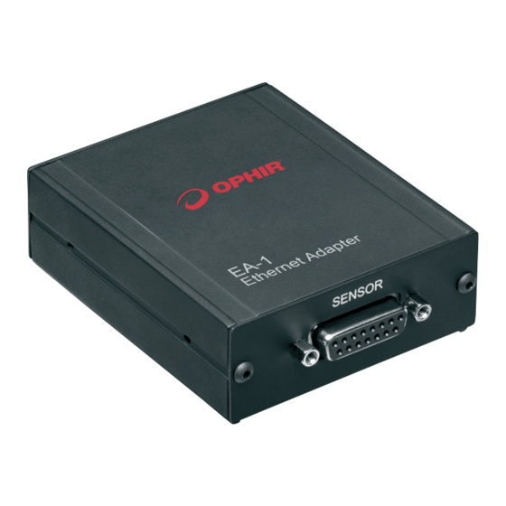
- Page 1 EA-1 EA-1 Ethernet Adapter User Manual Ophir Optronics Solutions Ltd.
-
Page 2: Table Of Contents
Contents About this document: ............................... 4 Definition of Terms: ..............................4 Chapter 1 - Introduction: ..............................5 General Description: ..............................5 Package Contents: ................................. 6 Connection Protocols: ..............................6 Ethernet Cables and Ground Connections to EA-1 Device: ..................7 Chapter 2 - Configuration: ..............................8 Device Default Configuration: ............................ - Page 3 Log Files and Buffer Files: ............................29 Chapter 5 - Other Features and Protocols: ........................31 Using HTTP Protocol: ..............................31 Searching for EA-1 Devices on the Network: ......................31 Summary of TCP Port Numbers: ..........................32 Chapter 6 - Details of User Commands: .......................... 33 General Rules: ................................
-
Page 4: About This Document
About this document: This manual contains instructions for using the Ophir “EA-1 Ethernet Adapter” device. The manual is divided into several sections: Introduction to the EA-1 and general description of the product Instructions for initial configuration and setup ... -
Page 5: Chapter 1 - Introduction
Chapter 1 - Introduction: This chapter provides some basic information about the EA-1 and a general description of the device. General Description: The EA-1 is an Ethernet Adapter intended for OEM customers. It is designed to work with standard or OEM Ophir smart-plug sensors using a D15 connector. -
Page 6: Package Contents
On the sides: Two M3 mounting holes are provided along each side of the device allowing attachment of an optional bracket (as shown in the illustration above). The bracket makes it easier for the customer to attach the device into his mechanical system. A set of two brackets and four screws are supplied with the device. Full device specifications are included in Appendix A below. -
Page 7: Ethernet Cables And Ground Connections To Ea-1 Device
commands directly using the HTTP protocol. As for the Telnet connection, the host device is the “client” and the EA-1 device is the “server”. Details are listed later on in this document. UDP: For situations where Telnet is not available (for example - working with some PLCs) another option is to connect to the device using a UDP connection. -
Page 8: Chapter 2 - Configuration
Chapter 2 - Configuration: Configuration of the EA-1 adapter is necessary before using the device for the first time. In particular, the IP address (and other related settings) must be set. Two IP address modes are supported - static allocation (default) or dynamic allocation (using DHCP). - Page 9 An IP address for the EA-1 adapter needs to be obtained from the network administrator; this example uses an IP Address 172.16.16.49, Subnet Mask 255.255.255.0 (default), IP Gateway 172.16.16.1 Note: In order to connect to the device using a PC, it may be necessary to first set the PC to a static IP address. Instructions for doing this are shown in Appendix 2 below.
-
Page 10: Setting Up A Static Ip Address Using Telnet
The settings have been saved in the device EEPROM but will only become active after the next power up of the device. Before disconnecting, repeat the above process for the Subnet Mask and Default Gateway settings, and press “Save” for each one. See example above (on the right). Now the device should be powered down (if using PoE, disconnect the Ethernet cable;... - Page 11 Check the “Telnet Client” option is switched on, then click “OK” and close the window. To open the Telnet connection, go to a command prompt window. Go to the “Start” button, click in the “Search programs and files” box, and type “cmd”, then <enter>: Alternatively, open windows explorer and navigate to the folder “C:\windows\system32\cmd.exe”...
-
Page 12: Setting Up A Static Ip Address Using The Usb Virtual Com Port
$NS 1 172.16.16.49 <enter> writes the new IP address into the local EEPROM, response should be “SAVED (need reset)” $NS 2 <enter> queries the present setting of Subnet Mask $NS 2 255.255.255.0 <enter> writes the new Subnet Mask value into the local EEPROM, if the value was changed the response should be *SAVED (need reset) $NS 3 <enter>... - Page 13 Using the “Set IP Address” button on the main window is the simplest method. This method will work even if the present IP address does not match the network to which the EA-1 is connected, for example the first time it is used. Open the application, choose a sensor, and click on “Set IP Address”: Then click on “Use current network settings”...
-
Page 14: Changing To Dynamic Ip Address Allocation Mode
Click on Set IP Address and follow the instructions above to fix the IP address to a good value. Using the “Setup Device” screen: An alternative method to change the IP settings is to use the “Select-Device” screen. After selecting the sensor in the main window (by clicking on it in the “Sensor Choice”... -
Page 15: Setting The User Device Name
Several software commands are provided to enable or disable dynamic allocation mode, and to query the IP Address allocated and the other device settings once it is enabled. These commands are listed in the Software Commands section below. In order to send these commands, a connection must be established with the device using one of the methods described above (HTTP, Ethernet, or USB VCP). -
Page 16: Returning To Factory Default Settings
Choose the correct new setting and then press “Save”. This has to be done once before using the device and is stored permanently in the device memory thereafter. The default factory setting is 50Hz. The same thing can be done by sending the series of commands $MA 1|2 (use parameter 1 for 50Hz, 2 for 60Hz), followed by $IC (see details below). -
Page 17: Chapter 3 - Http And The Built-In Web Server
Chapter 3 - HTTP and the Built-In Web Server: The EA-1 Adapter has a web server built into its firmware, allowing the user to perform simple tasks via a standard web browser such as Internet Explorer. Tasks that can be performed via the web server include: ... - Page 18 A full list of user commands is included at the end of this manual. To view the power being measured by the attached sensor, return to the “Start Page” and click on the “Power Monitor” button. The following page will be displayed: The latest power measurement will be displayed in red as in the example above.
-
Page 19: Chapter 4 - Using The "Ophirethernetapp" Application
Chapter 4 - Using the “OphirEthernetApp” Application: The most convenient way to get started with the EA-1 Adapter is to use the PC Application “OphirEthernetApp” supplied with the device. This chapter explains how to use the application. Getting started: The PC application is provided as a setup file which is self-installing. The name of the installation file is: “OphirEthernetApp-1.xx.exe”... -
Page 20: Choosing Network
On opening the application, or after clicking on “Search Sensors”, the application searches for all Ophir EA-1 Adapters it can locate on the network and lists them in the box shown above, with details of the sensor attached to each device. While performing the search, the mouse icon is changed to the “busy” symbol. The search includes devices it can locate either via Ethernet or via the USB Virtual COM Port connection, if present. -
Page 21: Choosing Measurement Range
Choosing Measurement Range: Choose the power or energy range using the drop down “Range” menu as shown: In most cases, an AUTO range option is available, allowing the sensor to choose its own best measurement range based on the present power incident on sensor. Alternatively the customer can choose manually from the available ranges, shown in descending order. -
Page 22: Choosing Wavelength Option, Calibration Curve
Choosing Wavelength Option, Calibration Curve: Some sensors, such as photodiodes and some types of thermopiles, contain a calibration curve over a certain range of wavelength. With these sensors, the user can choose up to six “favorite” wavelengths, which can be chosen using the simple drop down as for the Discrete Laser Points mentioned above. -
Page 23: Saving The Startup Settings
Select the wavelength option to remove and click on “Remove”, and that wavelength will be removed from the list. After making any selection or modifying the favorites, if the user wants to keep the present setup after the next startup, he can click on the Save Startup button as mentioned below. Saving the Startup Settings: In order to save the present settings of measurement range and favorite wavelength as the default startup settings, click on the “Save Startup”... - Page 24 On sensors that do not offer energy measurements, this button will be hidden from view. The energy measurement screen will open: The controls in the energy screen are similar to the power screen, except that the statistics are not available. In addition there is a status label just below the Energy value display, as shown below: Wait for the “READY”...
-
Page 25: Measuring Average Power For Low Frequency Pulsed Lasers - "Low Freq. Power Mode
Measuring Average Power for Low Frequency Pulsed Lasers - “Low Freq. Power Mode”: Starting from app & firmware v1.17 (Jan. 2019), a second method to measure average power on photodiode sensors is to use the “Low Freq. Power Mode”. This method is useful when measuring average power for pulsed lasers with frequency in the region of ~5Hz to ~100Hz. -
Page 26: Configuration And Setup
high, or the peak power is saturating the electronics. Note that when using this mode, the EA-1 device can sometimes be in saturation before the average power level exceeds the maximum power defined for the selected range. This is because the peak power of a pulse laser may exceed the allowed peak power for the selected power range. -
Page 27: Firmware Upgrade
Firmware Upgrade: The “OphirEthernetApp” software allows the user to upgrade the firmware loaded into the EA-1 device. This should be done only when a new version firmware is available from Ophir: The software will first check for a new firmware BIN file in the local sub-folder “Firmware” and will notify if a firmware upgrade is really necessary. -
Page 28: Zeroing
Sometimes a new version of firmware may be released on the Ophir website separately from the PC Application installation file. In that case, it will be necessary to copy the firmware “BIN” file (“EA1Axxx.bin”) to the local firmware folder of the PC Application (as defined above). The next time the PC Application is started up with the EA-1 attached, the application will prompt to upgrade the firmware. -
Page 29: Log Files And Buffer Files
Log Files and Buffer Files: The “OphirEthernetApp” application automatically creates log files while the sensor window is open and the sensor is measuring. These log files are located in the “My Documents” folder under “\OphirEthernetApp\”. The files are stored in “CSV” format, which is a comma delimited text file that Microsoft Excel can open directly. A new log file is created each time the sensor window is opened, and closed when the sensor window is closed. - Page 30 communication commands between the EA-1 device and the computer via the Telnet channel. This buffer file is a useful way to check which commands are being used by the application, and as a way to provide examples when writing custom software to talk to the device. It is also useful for debugging in case there are errors or problems with the software - the buffer file can be sent to Ophir to investigate any problem that might occur.
-
Page 31: Chapter 5 - Other Features And Protocols
Chapter 5 - Other Features and Protocols: This chapter contains some general information about connecting with the EA-1 device using other methods and querying Ophir devices on the network using the UDP Protocol. Using HTTP Protocol: Using an HTTP connection, commands can be sent directly to the device using the IP address and some extra characters. -
Page 32: Summary Of Tcp Port Numbers
Summary of TCP Port Numbers: By convention TCP uses the following port numbers: Connection: Port Number: Telnet HTTP 11000 EA-1 User Manual... -
Page 33: Chapter 6 - Details Of User Commands
Chapter 6 - Details of User Commands: The intended use of the EA-1 Adapter is for OEM customers who wish to embed the device inside their own laser system. In order to allow customers to control the device using their own software package, a set of “User Commands”... -
Page 34: Udp Protocol
UDP Protocol: If using a UDP connection, a special protocol is defined to enable sending commands to the device and receive back replies. This sub-section details the special UDP protocol. In order to send commands to the device via UDP: Send a UDP packet to device IP address port 11000 with the command string as defined here: Command String Format: OPHCMDXXXX$VE<params>[CR] where:... -
Page 35: Ethernet Commands
Ethernet Commands: These commands are specific to Ophir Ethernet devices and control the Ethernet settings and other related issues. Device User Name ($DN): Queries (with no parameter) or sets “Device User Name”. If present value is undefined, returns “?NOT DEFINED”. If parameter is “DELETE”, the present value is erased. -
Page 36: General Notes On Commands
Examples: $NP 1 -> “*IP : 172.16.16.42” $NP 2 -> “*Subnet Mask: 255.255.255.0” Network Dynamic IP Address Mode ($ND): This command sets, or queries the present setting, of DHCP (Dynamic IP address mode). Any changes will be used after the next device power up. Parameters: No parameter ->... -
Page 37: Device Specific Commands
Note: Some of the commands are specific to the type of sensor being used, for example some commands work only for energy mode; other commands work only with sensors which have a continuous calibration curve (all photodiodes and some thermopiles) rather than discrete calibration points (some thermos). Some commands work only with thermopile or only with photodiode sensors. -
Page 38: Zeroing Commands
Mains Setting ($MA): $MA <1 | 2>[CR] -> * 1 50Hz 60Hz[CR][LF] {Sets the internal measurement period used for sampling data to either 20ms for 50Hz regions, or 16.666ms for 60Hz regions. In some cases this can reduce noise. Sending the command with no parameter queries the present setting;... - Page 39 All Ranges ($AR): $AR[CR] –> * 2 AUTO 10.0W 3.00W 300mW 30.0mW [CR][LF] {Returns a list of all available power ranges (scales) (or energy scales if sensor is set to measure energy) including an index value showing which range is presently selected. In the example shown above, top scale (index 0) is 10W, scale 1=3W, scale 2=300mW, scale 3=30mW, and an auto- ranging scale is also available ("AUTO"...
-
Page 40: Using The Low Freq. Power Mode (Photodiode Sensors)
Using the Low Freq. Power Mode (Photodiode Sensors): This section is relevant for photodiode sensors measuring low frequency pulsed sources, such as VCSELs. This measurement mode is available using firmware 1.17 or above. See notes above on “Low Freq. Power Mode” for the PC application for more details. - Page 41 Send Energy Command ($SE): $SE[CR] -> *1.2345E1[CR] (Energy in Joules), or “*OVER[CR]” {Returns latest energy value measured in Joules, or "OVER" if last energy measurement was overrange. Returns "?NOT MEASURING ENERGY[CR]" if sensor is not measuring energy but only power} Notes: The Energy value is returned using same format defined for $SP.
-
Page 42: Wavelength Commands
tell the application that this value was ‘over-range’, and that it should change to a higher energy scale before continuing (or reduce the energy of the laser). Continue sending the $EF command until seeing "1" again, and then continue as above from. After changing energy range using $WN command, the sensor takes several seconds to settle before allowing energy measurements to resume. -
Page 43: Continuous Send Commands
"CONTINUOUS" indicates that this sensor contains a laser calibration curve. In this case, the user can select any wavelength within the min and max limits of the curve configured inside the sensor, and also choose up to 6 "favorite" wavelengths that are more easy to choose using the $WI or $WL commands, see below. "200"... -
Page 44: Misc. Commands
As opposed to the more normal "Command/Reply" mode that is used for most other commands such as $SP, $VE, "Continuous Send" mode places the device into a state where it transmits data continuously to the PC without being specifically requested to. This mode can sometimes make the software support easier inside a PC application supporting the device, and reduces the amount of communication overhead necessary to achieve the same thing using Command/Reply mode. -
Page 45: Commands For Pyroelectric/Pd-C Sensors
$DP 0 - enables polling until next reset $DP 1 - disables polling until next reset $DP 2 - enables polling permanently (responds “0”) $DP 3 - disables polling permanently (responds “1”) Note: Factory default is polling enabled; the result of disabling is that if a sensor is swapped over, the software (firmware and host application) will not be aware of the change and will carry on assuming nothing has happened. -
Page 46: Continuous Send Modes For Pyroelectrics/Pd-C Sensors
The commands supported are: $FE, $EF, $SE. For higher performance, and in particular for higher data rates when using fast pulsed lasers, use the “Continuous Send” mode instead as described in the following section. Diffuser Query ($DQ): $DQ -> *1 OUT IN[CR] {This command queries or changes the setting for diffuser in/out for sensors which contain a removable diffuser. - Page 47 1. ASCII MODE $CS 2 (max data rate ~14kHz): Using this mode, energy data is returned in a simple ASCII format with 4 significant digits. Data is terminated with the Line Feed/Carriage Return characters, in a similar way to responses from a regular command. Once per second, frequency data averaged over the last second is provided with the additional key word “FREQ”.
- Page 48 Details of Binary Mode: In Binary Mode, data is delivered in large blocks. A block consists of a 16-byte header followed by multiple data packages (8-bytes each). The header contains information about the number of bytes included in the block, a counter, and some fixed value bytes which allow the user to synchronize the data.
-
Page 49: Appendix 1 - Device Specifications - Ea-1 Ethernet Adapter
Appendix 1 - Device Specifications - EA-1 Ethernet Adapter: Specifications, Thermopile & Photodiode Sensors: Input Ranges 15nA - 1.5mA full scale in 16 ranges A-to-D Sampling rate 15Hz A-to-D Resolution ~17 bits plus sign Electrical accuracy ±0.25% ±20pA new; ±0.5% ±50pA after 1 year Electrical input noise level 500nV or 1.5pA + 0.0015% of input range @3Hz. -
Page 50: Appendix 2 - Configuring A Pc To Connect Directly To The Ea-1 Device
Appendix 2 - Configuring a PC to Connect Directly to the EA-1 Device: This Appendix describes how to set up a PC in order to connect using default EA-1 device IP Address 10.0.0.2, to configure the IP address. The PC is changed from using a Dynamic IP address to using a static IP address of 10.0.0.3 and the default gateway is changed to 10.0.0.1. - Page 51 Changing the PC IP settings using Windows 7: Go to: Control Panel -> Network and Sharing Center -> Change adapter settings (on left panel, shown below) Properties Select “Local Area Connection”. (Tip - connect the cable from the PC to the EA-1 device before entering this screen, otherwise the Local Area Network connection may not be displayed) Double-click, or right click and choose “properties”, to open its properties screen.
- Page 52 Using Windows 8, 10: Not tested, should be similar to Windows 7. Checking communications using Telnet: Open a command window (Start Menu -> Run -> cmd <enter> ) and type “telnet 10.0.0.2” to open a “Telnet” connection to the device. Then type commands to send to the EA-1 device such as “$VE<enter>”...
- Page 53 As an example, let's assume the IP address of the PC is 172.16.18.50, the Subnet Mast is 255.255.252.0, and the Default Gateway is 172.16.16.1 (as shown in the example). e. Connect the EA-1 device to the PC using both the USB and Ethernet cable, and connect the power cable to the EA- 1.
- Page 54 l) If using StarLab 3.30(+), the IP address will have to be set up correctly in the settings screen. Look for this icon in the Select Devices screen (below). The EA-1 device should be detected in the "Available Devices" list. Add the device to the list of "My Devices"...
-
Page 55: Appendix 3 - Considerations Regarding Cables And Grounding
Appendix 3 - Considerations Regarding Cables and Grounding: This appendix discusses types of Ethernet cable that should be used with the EA-1 device. Ophir supplies a short “cross-over” cable along with the EA-1 device, which can be used for initial setup if required. A “cross-over”... -
Page 56: Appendix 4 - Version History
Appendix 4 - Version History: [Any questions? Errors in the document? Please contact Julian.Marsden@ophiropt.com with your comments] v1-v9 - Older versions of application v10 15-Apr-18 (PC app rev 1.14; firmware v1.14-2) Updated instructions for telnet connections on windows 7 & laptops. Expanded Appendix 2 on how to connect between laptops/PC and EA-1.
Need help?
Do you have a question about the Ophir EA-1 and is the answer not in the manual?
Questions and answers