
Summary of Contents for Formula Air AADA Series
- Page 1 Pneumatic sliding dampers AADA, ABDB, CADB & CBDB Maintenance manual (EN) V1.0-2021 Maintenance manual | Electro-pneumatic sliding dampers www.formula-air.com...
-
Page 2: Table Of Contents
Content Introduction ..............................3 1.1. How it works ............................3 1.2. Product code description ........................4 1.3. Catalogue options ..........................4 Technical information ............................4 2.1. Sliding damper composition ........................4 2.1.1 For sliding dampers with ROUND cylinders ..................... 5 2.1.2 For sliding dampers with SQUARE cylinders .................... -
Page 3: Introduction
Introduction This manual cannot be reproduced, even partially, without prior written consent by Formula Air Group. Every step of the electro-pneumatic sliding damper range has been deeply analyzed by Formula Air Group in the expected area during the design, construction, and user manual creation. However, it is understood that nothing can replace the experience, training and good sense of those professionals who work with the device. -
Page 4: Product Code Description
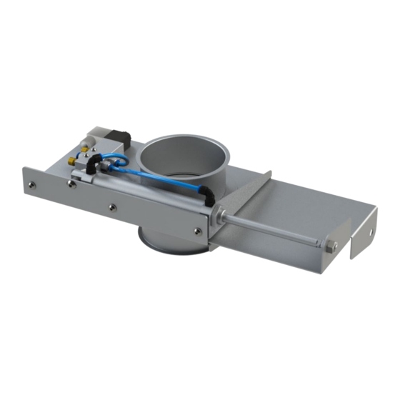
CLOSED POSITION OPENED POSITION 1.2. Product code description AADA : Medium pressure electro-galvanized sliding damper ABDB : Medium pressure stainless steel sliding damper CADB : High pressure electro-galvanized sliding damper CBDB : High pressure stainless steel sliding damper 1.3. Catalogue options The standard Pneumatic sliding dampers are available with the following configurations : - Different solenoid valve models : - Electro-pneumatic (standard) -
Page 5: For Sliding Dampers With Round Cylinders
2.1.1 For sliding dampers with ROUND cylinders Picture Part Quantity Body – ready for – AADS Solenoid valve with connectors 1 (from Ø80 up to Ø160) Solenoid valve with T connectors 1 (from Ø180 up to Ø500) 1 (up to Ø160) Pneumatic cylinder 2 (from Ø180 up to Ø500) Bolt M4 x 25... -
Page 6: For Sliding Dampers With Square Cylinders
2.1.2 For sliding dampers with SQUARE cylinders Picture Part Quantity Body – ready for – AADS Solenoid valve with connectors 1 (from Ø80 up to Ø160) Solenoid valve with T connectors 1 (from Ø180 up to Ø500) 1 (from Ø80 up to Ø160) Pneumatic cylinder 2 (from Ø180 up to Ø500) 1 (from Ø80 up to Ø160) -
Page 7: Electro-Pneumatic Solenoid Valve Details
D int. Edge Ø 13.3 13.3 19.7 1058 20.6 1058 20.6 1162 27.9 1316 40.9 1491 59.5 1635 67.8 2.3. Electro-pneumatic solenoid valve details Solenoid Operating Min. response Action Working Tº Nº cylinders valve type pressure time From Ø 80 up to Ø... -
Page 8: Mounting The Cylinders On The Body
CAUTION ! The mounting of the sliding damper has to be performed by qualified personnel only. Before starting assembling, check that you have all the parts and the correct tools for mounting. CAUTION ! Make sure to wear the appropriate protective clothing, gloves, eye protection and masks when needed. -
Page 9: For Sliding Dampers With Square Cylinders
Step 6 : Repeat steps 1 to 5 if the sliding damper is equipped with two cylinders. 3.2.2 For sliding dampers with SQUARE cylinders Step 1 : Screw the cylinder support to the base of the cylinder with the washers and bolts. Washer Bolt Step 2 :... -
Page 10: Mounting The Solenoid Valve On The Sliding Damper Body
3.3. Mounting the solenoid valve on the Sliding damper body 3.3.1 Mounting the solenoid valve on the sliding damper body Step 1 : Place the solenoid valve over the threaded holes on the sliding damper body. Step 2 : Screw the solenoid valve to the body with Hex-screws and washers. Bolts and washers 3.3.2 Mounting the coil and connector on the solenoid valve... -
Page 11: Mounting The Reed Sensors On The Cylinders (Optional)
Step 2 : Repeat for the other side of the cylinder. Then repeat to the other cylinder (if there is a second cylinder on the damper). Step 3 : Connect the air hose supply to the male stud connection on the other side of the electro-pneumatic solenoid valve (the side with the two regulators). -
Page 12: Electrical Connection Of The Reed Sensor
3.5.3 Electrical connection of the reed sensor 3.6. Mounting the cover house on the sliding damper body (optional) Step 1 : Unscrew the bolt from the damper body where the cover house goes. Step 2 : Slide the cover over the sliding damper body. Step 3 : Use the bolt unscrewed in Step 1 to attach it to the sliding damper. - Page 13 Attach together with pull rings Attach together with pull rings IMPORTANT : Make sure to use adequate support on the pipes on either side of the sliding damper to reduce pressure on the sliding damper body and blade. Recommended mounting in horizontal ducting is to have the blade open downwards, and have the sliding damper body supported with suspension rings at most at 150 mm from either side of the sliding damper edges.
-
Page 14: Maintenance, Spare Parts And Troubleshooting
Maintenance, spare parts and troubleshooting The installation, connection, start-up and maintenance of the sliding damper has to be performed by qualified personnel only. 4.1. Precautions for proper use CAUTION ! It is strictly forbidden to work on the electro-pneumatic sliding damper while the installation is running. During maintenance keep the system disconnected and all the electrical equipment turned off. -
Page 15: Troubleshooting
4.4. Troubleshooting Failure Possible causes Proposed solutions Make sure there is nominal current • No current (point 3.3) • No electrical reaction but Inverse or wrong wiring Refer to the wiring diagram (point • • there is compressed air Connector electrical overload 3.3) •... -
Page 16: Maintenance Log
Maintenance log date description Maintenance manual | Electro-pneumatic sliding dampers www.formula-air.com... -
Page 17: Contacts
+32 81 23 45 71 +370 41 54 04 82 +31 492 45 15 45 info-be@formula-air.com info-lt@formula-air.com info-nl@formula-air.com Formula Air France – North Formula Air France – East Formula Air France – West Sales Sales Sales Zac de la Carrière Dorée...
Need help?
Do you have a question about the AADA Series and is the answer not in the manual?
Questions and answers