Table of Contents
Advertisement
Quick Links
Advertisement
Table of Contents

Related Manuals for Toledo Transducers MoniTTor N269

Summary of Contents for Toledo Transducers MoniTTor N269
- Page 3 N269 Installation and Operations Manual...
- Page 4 THIS PAGE INTENTIONALLY LEFT BLANK...
-
Page 5: Table Of Contents
N269 Manual Table of Contents I.D. Page Warranty Page 1 Figure 1 - Enclosure Mounting Dimensions Page 2 Figure 2 - AC Power Hookup Page 4 Figure 3 - Sensor Hookup Page 5 Figure 4 - Main PC Computer Interface Wiring and Settings Page 6 Figure 5 - N269 Front Panel Page 7... - Page 6 G. Other Information……………………………………………………………………...………Page 27 1. The Last Alarm Page 27 2. The Last High Alarm Page 27 3. The Last Low Alarm Page 28 4. The Highest Load Page 28 5. The Lowest Load Page 28 6. The Production Rate in Strokes per Minute Page 28 7.
- Page 7 INSTRUMENT IDENTIFICATION Name AUTOMATIC PROCESS CONTROL LOAD MONITOR Model No. N269 Serial No. Date Shipped Company: (name) (street address) (city - state - zip) (telephone number) Purchase Order No. Invoice No.
-
Page 8: Warranty
LIMITED WARRANTY This unit is warranted by the manufacturer, Toledo Transducers, Inc., to be free of defects in workmanship and material for one year from date of manufacturer’s shipment. This warranty is limited to repairing or replacing products which manufacturer’s investigation shows were defective at the time of shipment by the manufacturer. - Page 12 FIGURE 3 Sensor Connections – N269 (RV7)
- Page 15 FIGURE 6 - Keyboard Jumpers and Switches JUMPER SETTINGS J2 - TRANSMIT TO MAIN PC ENABLE POS. A = RS422 POS. B = RS232 J3 - TRANSMIT TO AUX. DISPLAY ENABLE POS. A = RS422 POS. B = RS232 J4 - RECEIVE FROM MAIN PC SELECT POS.
- Page 16 FIGURE 7 - N269 Process Control Zone Chart This meter is designed to determine the peak load on each cycle of the press and respond to the load by operating the appropriate relays. The 4 variable setpoints establish the 5 zones shown on the sketch.
-
Page 17: N269 Operators Guide
N269 OPERATORS GUIDE TURN ON POWER - The first time power is applied all values are set to 0.0 except for the following: CAPACITY = 100.0 each chan THRESHOLD = 6.3 chan 0 HIGH SETPOINT = 100.0 each chan DIFFERENCE SET = 100.0 chan 0 LOWEST LOAD = 100.0 each chan COUNT HIGH SET = 100.0 chan 0 OPERATING MODE = PEAK mode... -
Page 18: General Description
GOOD PART RELAY TIME GOOD 0 (value) ENTER REJECT RELAY TIME REJECT 0 (value) ENTER DECREASE RELAY TIME DE 0 (value) ENTER INCREASE RELAY TIME IN 0 (value) ENTER PRESET COUNTERS To display press: To change press: SHUTDOWN RELAY TIME REJECT . - Page 19 The N269 process control load meter is used to control the variable material fill of a press on the basis of the peak load. System input can be from one or two strain gage bridge type sensors. In a single channel system the input is usually a load cell. Systems with two channels generally use two press frame mounted load sensors.
-
Page 20: Operation
display goes blank. Several operating modes can be selected in addition to the normal peak mode. Setup mode disables all relays. Reverse mode shows any reverse loading taking place. A time delay starting at the beginning of the load cycle can be set to use the load at a particular point the stroke. First level mode is the peak load up to the time point. -
Page 21: Load Display
At any given time the N269 will be showing one of three displays: the load for the last stroke according to the operational mode along with the process control setpoints, other information as requested by the user, or new data entered via the keyboard. These displays will be referred to as the load display, the data display, and the data entry display. -
Page 22: Key Sequences
DISPLAY with all channels lit once again, displaying what was displayed when they went blank during the last data entry. Now another channel may be selected and data entered, other data displayed, or load may be displayed once again by pressing "RESET". DATA ENTRY DISPLAY may only be changed via the "ENTER"... -
Page 23: Setting The Relay Timers
determines how long the relay stays on when activated. The REject relay operates at the end of the stroke if the channel 0 load was in either the high-reject zone or the low-reject zone. The GOod part relay operates at the end of the stroke if the channel 0 load was in the good zone. -
Page 24: Setting The Relay Preset Counters
does not operate. To enable the process control relays to operate a time must be entered for each relay. To enter a time for the GOod part relay press the keys: TIME GOOD 0 (data) ENTER. To enter a time for the REject relay press the keys: TIME REJECT 0 (data) ENTER. -
Page 25: Low Setpoints
displayed. Setpoint #3 is the reject-hi setpoint and setpoint #4 is the decrease fill setpoint. To display the HIGH SETPOINTS, press the "HIGH" key once. Remember that if this key is part of another valid sequence it may be necessary to press "RESET" once first. The HIGH SETPOINT for each channel will be displayed in its own channel. -
Page 26: Resetting Alarms
SETPOINT for each channel will be displayed in its own channel. The LOW LEDs will be lit in each channel to indicate that the LOW SETPOINTS are being displayed. Low LEDs not lit indicate bypassed LOW SETPOINTS in the corresponding channel. To enter new LOW SETPOINT values press the number key (0-2,5,6) of the channel you wish to change. -
Page 27: The Batch Counter
Each load stroke of the press is counted. To display the COUNT press the "COUNT" key. "COUNT" is a part of several key sequences so you may need to press "RESET" before pressing "COUNT". The COUNT appears as an 8 digit number in channel 0. The COUNT is cleared to 0 by pressing the "CLEAR"... -
Page 28: The Alarm Counters
To view the number of GOod part relay operations press: COUNT GOOD To view the number of DEcrease relay operations press: COUNT DE To view the number of INcrease relay operations press: COUNT IN Each stroke of the press the channel 0 load falls into one of 5 zones determined by the 4 process control setpoints. -
Page 29: Low Counters
press the "CLEAR" key while the counts are being displayed. The HIGH ALARM COUNT for each channel is cleared to 0. "ENTER" need not be pressed. b. LOW COUNTERS - COUNT LOW The LOW ALARM COUNTS are only valid for meters with more than one sensor input. -
Page 30: Setting The Time Value
TIME mode number Special operating mode B4 mode First level mode Second level mode Point-in-time mode b. SETTING THE TIME VALUE - TIME [ 0 (VALUE) ENTER] A TIME VALUE may be entered which, when used with TIME mode described below, can show the peak load for various portions of the stroke. -
Page 31: The First Level Load
single digit number. Press the number 3 key. Now press ENTER. The meter is selected for time mode number 3 but may not yet be selected for TIME mode itself. If the TIME LED is lit, the meter is already in TIME mode. Just press RESET and the Point-In-Time load will be displayed. If the TIME LED is not lit, press the TIME key twice to light the TIME LED thus putting the meter in TIME mode. -
Page 32: The B4 Mode
f. THE B4 MODE The B4 mode is a combination of the normal peak mode and first level mode. This mode is meaningful only for presses with more than one sensor input. When selected the B4 mode displays the distribution forces at the first level time in channels 1 and 2. Then when the punch finishes the stroke the total load is displayed in channel 0. -
Page 33: Other Settings
The REVERSE mode changes the polarity of the input analog signal. The main use of this mode is to read "snap-through" loading which occurs primarily in blanking operations. To enter REVERSE mode press the "REV" key. The REVERSE LED will light indicating the mode change. Pressing the "REV" key again will take the meter out of REVERSE mode extinguishing the REVERSE LED. -
Page 34: Other Information
sequence at the keyboard. When this is done, all memory values are cleared to 0 except for the CAPACITY, the DECIMAL POINT number, the THRESHOLD, the TIME value, and the MAXIMUM CHANNEL number. A few other values are set to the same value they would have if they had never been entered. The high setpoints are set to capacity in each channel. -
Page 35: The Highest Load
Last Low Alarm an is updated whenever another low alarm occurs. This information about the Last Low Alarm can be recalled to the display by pressing the proper key sequence at the keyboard. To display the Last Low Alarm load information press the key sequence LOW TIME. -
Page 36: The Diagnostics
time a new stroke occurs this time is reset to 0. To display the down time, press the key sequence TIME COUNT. The channel 0 display will show three numbers separated by spaces. These numbers are from left to right, days, hours, and minutes since the last stroke. -
Page 37: Ac & Power Connections
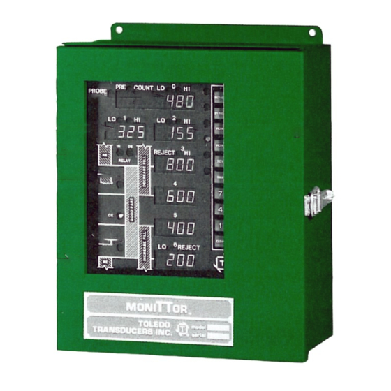
The N269 meter comes in a 14x12x6 green enclosure and should be mounted on or near the press so as to be easily seen by an operator. USE THE 4 SHOCK MOUNTS PROVIDED when mounting the enclosure to protect the electronic assemblies from excessive vibration. All wiring connections to the N269 are made through the bottom of the enclosure and should use flexible conduit. -
Page 38: Sensor Hookup
connection to the probes. See Figure 2 for more information. C. SENSOR HOOKUP - Refer to figure 3 Sensors should be wired with the power OFF. If the meter has already been powered up power can be shut off by removing the fuse. All sensor connections are made to the N269 main PC board through removable 5 pin terminal blocks. -
Page 39: Initial Settings
OPERATING MODE PEAK PRESET COUNTERS 1 for each relay LOWEST LO TONS 100.0 in each channel CNT HI SETPOINT 200.0 in channel 0 All other data is set to 0. Before using the N269 meter to accurately monitor tonnages the following must be done: 1. -
Page 40: The Probe Input
relieved. This triggering can be either internal or external to the meter. The internal method is by the use of the THRESHOLD. The THRESHOLD is the minimum total load which must be generated in channel 0 before the signal is recognized as a load signal. To view the THRESHOLD press the LOW key three times in a row. -
Page 41: Track (Calibration) Mode
5. TRACK (calibration) MODE - TRACK In TRACK mode the raw signal from each sensor scaled to the CAPACITY is shown in its corresponding channel. Channel 0 shows the total of channels 1 and 2. When only one sensor is connected (into channel 1) channel 0 shows that single sensor signal. -
Page 42: Calibration
PEAK mode is entered by pressing the "PEAK" key. When pressed, the PEAK LED will light and the TRACK LED will go out. The PEAK values of the last load cycle will be displayed in each channel. Peak is the normal operating mode of the N269 meter. F. -
Page 43: Calculated Calibrations
2. CALCULATED CALIBRATIONS If the precise area of the member to which the strain gage is attached is known, sometimes a calculated calibration can be given. In this case a specification sheet is provided showing the proper calibration numbers for each channel. Also shown on this sheet is the proper setting of the LOW-HIGH GAIN switch for both calibration and normal operation. -
Page 44: Rs422 Interfaces
connector) located at the right edge of the main PC board. This connector is labeled: - T + GND - R +. 1. RS422/RS485 INTERFACES The wires to the computer should consist of three twisted pairs with an overall shield. We recommend BELDEN #8013 cable for this application. -
Page 45: Troubleshooting Information
computer at the right edge of the main PC board. Switches #4-#8 of SW11 select this address. The following example shows the proper switch settings for various meter addresses. DO NOT SELECT THE SAME ADDRESS FOR MORE THAN ONE METER ON EACH RS422 LINE. SW 11 - Down = 1 Down = 2... -
Page 46: Symptoms And Solutions
located in the lower middle section of the main PC board. There are two rows of pins: the front (lower) row of pins is the analog output for the channels starting with channel 0 at the left end; the rear (upper) row of pins is the signal ground. These pins are such that scope probe may be clipped to the pin or a mating connector may be attached to all pins for sending the signals to a recorder, etc. -
Page 47: Transmission Characteristics
B. TRANSMISSION CHARACTERISTICS All data is ACSII characters 9 selected asynchronous baud rates 1 start bit, 8 data bits, 1 stop bit Modem controls not used Maximum information block size - 256 bytes Data must be transmitted as a block - no pause allowed C. -
Page 48: Data Type Character
"#" (23 HEX) Reset alarmed condition in N269 "%" (25 HEX) Clear all memory to initial state (27 HEX) Send data without spaces (like ") "-" (2D HEX) Enter mode information (8 digits) "." (2E HEX) Enter HIGH LED info (4digits) "/"... - Page 49 L = Low and Dif setpoints 0000 to 9999 CHAN 0 = Difference 0000 to 9999 CHAN 5 = Increase 0000 to 9999 CHAN 6 = Reject Lo 0000 to 9999 M = Last lo alarm 0000 to 9999 N = Normal peak load 0000 to 9999 O = Undefined P = Point in time load...
-
Page 50: Data - N269 Generated
CHAN 0 = Batch counter 0000 to 9999 upper 4 digits CHAN 1 = Batch counter 0000 to 9999 lower 4 digits CHAN 2 = Time since last dd0hh0mm total 8 digits CHAN 3 = Time since last dd=days, hh=hours, mm=minutes CHAN 4 = Decrease zone cnt 0000 to 9999 upper 4 digits... -
Page 51: Record
a. RECORD - [Header (2)], Data Type (1), Command (1), Mode (8), High LED (4), Low LED (4), Chan 0 (4), Chan 1 (4),...Chan N (4), Data Type (1), Command (1), High LED (4), Low LED (4), Chan 0 (4),..., Chan N (4),[Trailer (5)] The N269 data portion of the record starts with 2 bytes indicating data type and command (command will either be 22 HEX or 27 HEX). -
Page 52: High And Low Led Construction
c. HIGH AND LOW LED CONSTRUCTION (4 BYTES 30-3F HEX EACH) HIGH LEDs - 00110000 00110000 0011000X 0011XXXX | | | | Reject Hi zone-----------------------------------------------^ | | | | Decrease relay---------------------------------------------------------^ | | | CHANNEL 2-------------------------------------------------------------^ | | CHANNEL 1---------------------------------------------------------------^ | CHANNEL 0----------------------------------------------------------------- ^ X -- 1 = LED ON, 0 = LED OFF... -
Page 53: Checksum Calculation
THRESHOLD - The load generated in channel 0 must exceed this value before the stroke is recognized as valid. If this is 0, the meter uses the probe to trigger on. DELAY TIME - Wait in seconds from triggering point (threshold or probe) before the peak is read.
Need help?
Do you have a question about the MoniTTor N269 and is the answer not in the manual?
Questions and answers