
Related Manuals for Pulsar PG5250B


Summary of Contents for Pulsar PG5250B
- Page 1 Model:# PG5250B Generator OPERATOR’S MANUAL Warning: The Engine Exhaust from this product contains chemicals known to the State of California to cause cancer, birth defects or other reproductive harm. www.pulsar-products.com...
-
Page 2: Table Of Contents
TABLE OF CONTENTS Introduction.................................3 Parts Ordering / Customer Service.........................3 Product Specifications............................3 Safety Rules ................................4 Safety Symbols.............................. 4 Safety Instructions ............................4 Features..................................7 Assembly ................................... 9 Unpacking ..............................9 Packing List ..............................9 Attaching Wheels ............................10 Adding Oil/Checking engine oil ........................11 Adding Fuel. -
Page 3: Introduction
The emissions control system for this generator is compliant with all standards set by the U.S. Agency. How to contact us: To order parts, receive warranty assistance, or other services inquiries, you can contact us at www.pulsar-products.com PULSAR PRODUCTS INC... -
Page 4: Safety Rules
SAFETY RULES Safety Symbols Indicates a potentially hazardous WARNING! situation which could result in serious injury or death if not avoided. Indicates a potentially hazardous CAUTION! situation which could result in damage to equipment or property. Toxic Fumes Risk of fire Risk of explosion Risk of electric shock Hot surface... - Page 5 SAFETY RULES Never exceed generator’s wattage / amperage capacity. This could damage the generator WARNING! and / or connected electrical devices. Check operating voltage and frequency requirements of all electrical devices prior to plugging them into the generator. • Never start or stop engine with electrical devices plugged in to the receptacles. Failure to do WARNING! so could damage the generator and / or connected electrical devices.
- Page 6 SAFETY RULES This generator produces a very high voltage which could result in burns or WARNING! electrocution causing serious injury or death. • Never handle the generator, electronic devices, or any cord while standing in water, while barefoot, or when hands or feet are wet.
-
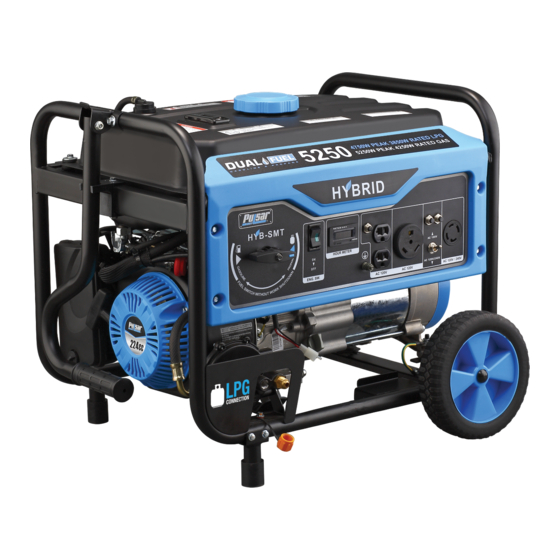
Page 7: Features
FEATURES A - ON/OFF Switch F - Two 120 V Receptacles B - Hour Meter G - 30 Amp RV Receptacle H - 120 / 240 Volt AC, 30 Amp twist lock receptacle (NEMA L14-30) C - Circuit Protectors I - Ground Terminal D - Main Circuit Breaker J - Fuel Selector Switch E - Voltage Selector... - Page 8 FEATURES K - Fuel Tank Vapor Vent R - Support Foot L - Fuel Gauge S - Fuel Cap M - Generator Frame T - Gas Tank N - Choke Lever U - Fuel Valve O - Air Filter V - Oil Fill (Dipstick) P - Pull Start W - Propane Inlet Q - Handle...
-
Page 9: Assembly
ASSEMBLY Unpacking 1. Place box on a level surface. 2. Remove all items from box except the generator. Make sure all items listed on the packing list are included and not damaged. 3. Cut down the sides of box being careful to avoid hitting the generator. 4. -
Page 10: Attaching Wheels
ASSEMBLY Attaching Wheels (See fig 1) • Parts needed - 2 wheels, 2 axles, 2 hair pins, and 2 washers. • Raise or tilt generator so you can slide the wheel axle pin into the wheel, the washer, the wheel mounting hole located on the side of the frame. -
Page 11: Adding Oil/Checking Engine Oil
ASSEMBLY Handle Assembly (See fig 3) • Install handle lock holder by inserting bolt and lock nut. (fig 3) • Install handle Bracket to frame with 2 bolts and lock nuts as shown on illustration. • Set handle in the bracket aligning the holes and insert handle bolt and lock nut. Fig 3 You must add oil before first operating this generator. -
Page 12: Adding Fuel
ASSEMBLY Adding Fuel (See fig 5) • Set generator on a clean and level surface in an area that is well ventilated. • Remove fuel cap. • Insert a funnel into the fuel tank and carefully pour gasoline into the tank until fuel level reaches 1 ½ inches below the top of the neck. -
Page 13: Operation
OPERATION Grounding the Generator (See fig 7) The ground terminal located on the back of the generator frame must always be used to connect generator to a driven ground rod. Connect the ground terminal to the driven ground rod with a No 8 AWG (American Wire Gauge) copper wire. The wire connects to the terminal between the lock washer and nut. - Page 14 OPERATION PROPANE Fig 9 Fig 8 Fig 10 START WAIT 5sec CHOKE CHOKE CHOKE LEVER CHOKE LEVER Fig 11 Fig 12 Recoil Start Fig 13 SKIP THIS IF THE ENGINE IS WARM OR HOT.
-
Page 15: How To Stop Engine
OPERATION Never start or stop engine with electrical devices plugged in to the receptacles. Failure to WARNING! do so could damage the generator and / or connected electrical devices. • Always start the engine and let it stabilize before connecting any electronic devices. •... -
Page 16: Don't Overload Generator
OPERATION 120 / 240 Volt AC, 30 Amp locking receptacle • This receptacle has a 30 Amp push-to reset circuit breaker to protect against overload. • This receptacle is rated to operate 120 Volt, AC, single phase, 60Hz loads requiring up to 3600 watts (3.6 kW) at 30 Amps. -
Page 17: Wattage Reference Guide
OPERATION 1. Add up the total rated wattage of all electronic devices that will be connected to the generator simultaneously. 2. Estimate surge watts by adding the item(s) with the highest output (it is unnecessary to calculate the surge output for all devices as they should be connected one at a time). -
Page 18: Cold Weather Operation
OPERATION Hour Meter (See Fig 18) Use this meter along with the manual to determine when and what type of service on the unit is needed. The display will show the word “LUBE” at the first 25 hours of operation and again at every 100 hours of operation after. Power Management Start engine without anything connected to the generator. -
Page 19: Maintenance
MAINTENANCE Regular maintenance will extend the life of this generator and improve its performance. The warranty does not cover items that result from operator negligence, misuse, or abuse. To receive full value from the warranty, operator must maintain the generator as instructed in this manual, including proper storage. Before inspecting or servicing this machine, make sure the engine is off and no parts are WARNING! moving. -
Page 20: Changing Oil
MAINTENANCE Changing Oil (See Fig 19) • Run the Generator until the Engine is warm. • Place generator on a level surface. • Remove the crankcase dipstick. • Place an oil pan underneath the oil drainage bolt to collect used oil. Oil Fill &... -
Page 21: Engine Maintenance
Spark Arrestor (See Fig 22) • Inspect the spark arrestor for breaks or holes. Replace if necessary. To purchase a replacement spark arrestor contact PULSAR customer service. • Use a brush to remove carbon deposits from the spark arrestor screen as needed. -
Page 22: Maintaining Fuel Valve
The effect of altitude on horsepower will be greater than this if no carburetor modification is made. Replacing Fuel Filter (See Fig 23 If Applicable) Occasionally the fuel filter may become clogged and need replacing. To purchase a replacement fuel filter contact PULSAR customer service or your local small Engine repair shop. -
Page 23: How To Store
MAINTENANCE Draining the carburetor • Turn the engine OFF. • Turn the fuel valve to the OFF position. • Position a suitable container under the carburetor drain screw to catch fuel; loosen the screw. • Allow fuel to drain completely into container. •... -
Page 24: Troubleshooting
TROUBLESHOOTING Problem Cause Solution Engine is running, but AC output is not 1. Open circuit breaker 1. Reset circuit breaker available 2. Poor connection 2. Check and repair 3. Defective cord set 3. Check and repair 4. Connected device is faulty 4. -
Page 25: Diagrams
DIAGRAMS... -
Page 26: Warranty
From the date of original purchase, Pulsar Products Inc. warrants to the original purchaser that each portable generator sold, shall be free from defect in material and workmanship for the items and time period set forth below. Pulsar Products Inc., at its discretion, agrees to repair or replace any defective part that upon examination, inspection, and testing by a Pulsar Products Inc. - Page 27 Take the original receipt and product to the place of purchase or mail the original receipt and product to the address found on the web site if purchased on-line. You can also locate your nearest Pulsar Products Inc. dealer for service or warranty questions by calling toll free at 1-866-591-8921.
Need help?
Do you have a question about the PG5250B and is the answer not in the manual?
Questions and answers