Table of Contents
Advertisement
Via delle Città, 41/43 50052 Certaldo (Firenze)
Tel. 0571. 65 12 04
Fax (ufficio amministrativo commerciale) 0571. 65 29 91
Fax (ufficio tecnico) 0571 65 08 98
Corrispondenza P.O. BOX 196 CERTALDO (FI) ITALY
Email:pertici@pertici.it
Instruction manual for use and maintenance
for WM1L/S WM1L/S-M WM1L/E Single
head machines
http://www.pertici.it
File: 1927.doc - 25/01/02 11:55
1
Advertisement
Table of Contents

Summary of Contents for Pertici WM1L/S
- Page 1 Fax (ufficio amministrativo commerciale) 0571. 65 29 91 Fax (ufficio tecnico) 0571 65 08 98 Corrispondenza P.O. BOX 196 CERTALDO (FI) ITALY Email:pertici@pertici.it http://www.pertici.it File: 1927.doc - 25/01/02 11:55 Instruction manual for use and maintenance for WM1L/S WM1L/S-M WM1L/E Single head machines...
-
Page 2: Table Of Contents
9.1 – PLATE CLEANING ....................32 9.2 –REPLACEMENT OF TEFLON................33 9.3 – PROTECTED MENU ................... 34 9.4 – RESET MEMORY ....................34 File: 1927.doc - 25/01/02 11:55 Instruction manual for use and maintenance for WM1L/S WM1L/S-M WM1L/E Single head machines... -
Page 3: Introduction
2.2 Safety in the use of the machine can only be guaranteed for the functions and materials listed in this instruction manual. PERTICI S.p.A. declines all liability if the machine is used for purposes other than those stated and in ways that do not conform to the user instructions. - Page 4 2.17 Always consider the possible consequences before approaching any of the more dangerous zones: heating plate area, pressor zone, welding seal limitation blades area. File: 1927.doc - 25/01/02 11:55 Instruction manual for use and maintenance for WM1L/S WM1L/S-M WM1L/E Single head machines...
-
Page 5: Characteristics
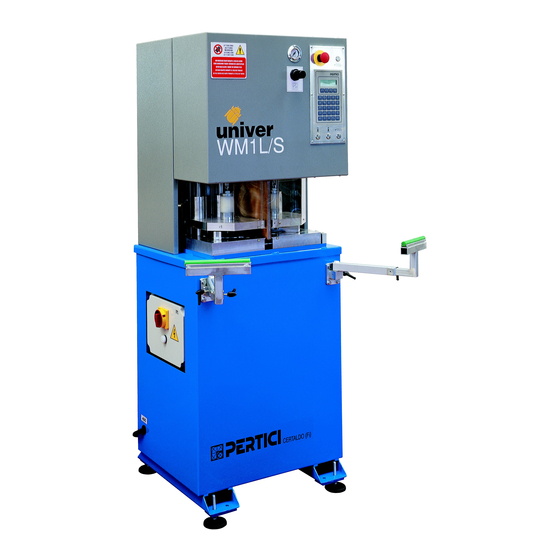
3. CHARACTERISTICS 3.1 Description of the machine The welding machines type WM1/LS – WM1/LS-M and WM1/LE produced by PERTICI S.p.A. are used mainly to weld at different angles, ranging from 180° to 40°. A) Base plate The base plate consists of a 3-mm thick sheet bed. (TAV. A1.1) The elements of the base plate are bent in order to obtain the maximum rigidity and are assembled by means of an intermittent weld. - Page 6 This type of solution is used above all when welding only white coloured PVC profiles. DWG. A1.2 DWG. A1.3 File: 1927.doc - 25/01/02 11:55 Instruction manual for use and maintenance for WM1L/S WM1L/S-M WM1L/E Single head machines...
- Page 7 The horizontal movement for plate centering is obtained by means of linear ball-bushings, which slide always on round section rods. File: 1927.doc - 25/01/02 11:55 Instruction manual for use and maintenance for WM1L/S WM1L/S-M WM1L/E Single head machines...
- Page 8 File: 1927.doc - 25/01/02 11:55 Instruction manual for use and maintenance for WM1L/S WM1L/S-M WM1L/E Single head machines...
-
Page 9: Technical Features
3.2 Technical features WM1L/S-M 3.3 Directly functioning components during welding In order to carry out the welding operation, the welding machines type WM1L/S – WM1L/S-M – WM1L/E use the following components: An aluminium plate heated by an electrical resistor. A set of 4 welding seal limitation blades (which can also be heated only for versions WM1L/S –... -
Page 10: Welding Seal Limitation Blades
The single head welding machines type WM1L are supplied complete with a set of 4 welding seal limitation blades. The WM1L/S and WM1L/S-M versions have removable welding seal limitation blades, which can also as an optional be heated. The economic version type WM1L/E has fixed welding seal limitation blades, engraved in the lower profile holding plates and in the upper profile locking plates (the type that can be heated can never be supplied in this case). - Page 11 WM1L/S – WM1L/S-M DWG. A1.7 WM1L/E DWG. A1.8 File: 1927.doc - 25/01/02 11:55 Instruction manual for use and maintenance for WM1L/S WM1L/S-M WM1L/E Single head machines...
-
Page 12: Use Limits
3.4 Use limits The welding machines type UNIVER WM1L/S - WM1L/S-M and WM1L/E, produced by PERTICI S.p.A. are used for welding of: profiles of plastic materials, mainly PVC (Polyvinyl chloride). The machines have been designed and built to be used in covered industrial environments. -
Page 13: Optional/Spare Parts
EN 292-1 (1991)and UNI EN 292, part 1, standards. EN 292-2 (1991) UNI EN 292, part 2, standards. EN 50081 - 1 (1992) standards. EN 50082 - 1 (1992) standards. File: 1927.doc - 25/01/02 11:55 Instruction manual for use and maintenance for WM1L/S WM1L/S-M WM1L/E Single head machines... -
Page 14: Commissioning
(DWG. A1.1). Avoid knocks, jolts and sudden movements when handling the machine. File: 1927.doc - 25/01/02 11:55 Instruction manual for use and maintenance for WM1L/S WM1L/S-M WM1L/E Single head machines... -
Page 15: Safety Zones And Dimensions
PERTICI SPA declines all liability for damages caused during shipment. It is therefore important to check the state of the packaging at the time of purchase. 4.3 Safety zones and dimensions Once the machine has been moved to the place of its definitive installation and the packaging has been removed, proceed with the installation. - Page 16 - Enter the arms (1) into supports (2) fixed on the base plate of the machine File: 1927.doc - 25/01/02 11:55 Instruction manual for use and maintenance for WM1L/S WM1L/S-M WM1L/E Single head machines...
- Page 17 (2). - Find the correct position and tighten the screws (4) completely. DWG.A1.13 DWG.A1.14 ATTENTION: CARRY OUT THIS OPERATION ON BOTH SIDES File: 1927.doc - 25/01/02 11:55 Instruction manual for use and maintenance for WM1L/S WM1L/S-M WM1L/E Single head machines...
-
Page 18: Compressed Air Circuit Hook-Up
The user's electricity network must comply with IEC 64-8 standards (CENELEC HD 384, IEC 364-4/41). The network must have: - a unipotential ground circuit; File: 1927.doc - 25/01/02 11:55 Instruction manual for use and maintenance for WM1L/S WM1L/S-M WM1L/E Single head machines... -
Page 19: Use
When this signalling lamp is on, means that the machine is energised (main switch turned to position “ 1” ). MAIN SECTION SWITCH POWER SIGN. LAMP DWG. A1.15 File: 1927.doc - 25/01/02 11:55 Instruction manual for use and maintenance for WM1L/S WM1L/S-M WM1L/E Single head machines... - Page 20 The PBSX PBDX push buttons are used to activate the locking cylinders for locking of pieces on the working surface. These push buttons must be kept pressed during the lowering of the locks. ATTENTION: IN CASE OF REPLACEMENT USE ONLY PERTICI ORIGINAL PUSH BUTTONS BI-MANUAL PUSH BUTTONS P1 P2 (DWG. A1.16) The P1 and P2 push buttons are used to start the working cycle and afterwards to carry out the automatic welding cycle.
- Page 21 If the other hand comes in contact with one of the blocking plates, a low tension electric circuit is closed which immediately inverts the movement of the blocking system. File: 1927.doc - 25/01/02 11:55 Instruction manual for use and maintenance for WM1L/S WM1L/S-M WM1L/E Single head machines...
-
Page 22: Operating Cycle
- Check if the pneumatic and the electric connection has been carried out. - Turn the main switch to position “ 1” - The display shows: WAIT FOR THE MACHINE AT TEMPERATURE T:210.0>245 T:35>40 File: 1927.doc - 25/01/02 11:55 Instruction manual for use and maintenance for WM1L/S WM1L/S-M WM1L/E Single head machines... - Page 23 - At the end of the machine movements release the two push buttons. The display shows: PBS=CLOSE/OPEN LE BLOCKING PBD=CLOSE/OPEN RI BLOCKING File: 1927.doc - 25/01/02 11:55 Instruction manual for use and maintenance for WM1L/S WM1L/S-M WM1L/E Single head machines...
- Page 24 - the display shows: COOLING SECONDS LEFT: 30 File: 1927.doc - 25/01/02 11:55 Instruction manual for use and maintenance for WM1L/S WM1L/S-M WM1L/E Single head machines...
-
Page 25: Emergency Device
When the trolley reaches the mechanical stop, the inductive sensor activates and give the enable signal to the PLC to go on with the working cycle. INDUCTIVE THERMOCOUPL SENSOR INDUTTIVO DWG. A1.19 File: 1927.doc - 25/01/02 11:55 Instruction manual for use and maintenance for WM1L/S WM1L/S-M WM1L/E Single head machines... -
Page 26: Reed Sensors
5.5.2 Reed sensors The Reed sensors (installed only on versions WM1L/S and WM1L/S-M) are installed on the cylinder for the vertical blocking, of the welding plate and of the right movable plane. These sensors do not need regulation in any case. In case of malfunction, the PLC will send a message on the display. -
Page 27: Precautions To Ensure Safety During Use
Never leave the already welded workpiece on the work surface: remove it immediately, to avoid leaving loose pieces of profile lying around on the work surface. File: 1927.doc - 25/01/02 11:55 Instruction manual for use and maintenance for WM1L/S WM1L/S-M WM1L/E Single head machines... -
Page 28: Adjustment Of Working Parameters
- The default alarm level is 5°C, should the temperature read by thermocouple be lower or higher than this level, the controller shows the message “ WAIT FOR TEMP. OK” . File: 1927.doc - 25/01/02 11:55 Instruction manual for use and maintenance for WM1L/S WM1L/S-M WM1L/E Single head machines... -
Page 29: Temperature Of Welding Seal Limitaton Blades (If Installed)
- The value indicated on the left is the one entered by the operator (in seconds). - Use the keyboard to enter the desired value and press ESC to exit and confirm the entered value. File: 1927.doc - 25/01/02 11:55 Instruction manual for use and maintenance for WM1L/S WM1L/S-M WM1L/E Single head machines... -
Page 30: Cooling Timer
Should the customer have requirements that differ from our standard, he may ask, when ordering or after the machine supply, to modify the above mentioned parameters. File: 1927.doc - 25/01/02 11:55 Instruction manual for use and maintenance for WM1L/S WM1L/S-M WM1L/E Single head machines... - Page 31 The company PERTICI s.p.a. will give or can give the necessary material to obtain the following mechanical welding parameters: WM1L/S – WM1L/S-M - Reduction of the welded profile length 6 mm (for each welded side) - Limitation of welding seal 2 mm (upon request 1 mm. – 0.2 mm)
-
Page 32: Servizi
ATTENTION: THE HEATING PLATE HAS A VERY HIGH TEMPERATURE (ABOUT 250°) ALWAYS USE SUITABLE GLOVES TO PROTECT THE HANDS FROM BURNS. TAKE ALSO THE UTMOST CARE DURING THIS OPERATION. File: 1927.doc - 25/01/02 11:55 Instruction manual for use and maintenance for WM1L/S WM1L/S-M WM1L/E Single head machines... -
Page 33: Replacement Of Teflon
(4), pull the cloth upwards so that it results perfectly flat on the plate surfaces and tighten nuts (2) (DWG. A1.2) completely. - Press ESC t exit and return to normal conditions (DWG. A1.22) File: 1927.doc - 25/01/02 11:55 Instruction manual for use and maintenance for WM1L/S WM1L/S-M WM1L/E Single head machines... -
Page 34: Protected Menu
Please call PERTICI technicians in case of need. 9.4 – RESET MEMORY This option could be useful in case of program updating operations, which need the memory reset. - Page 35 PAG.26 replacement of teflon TAB.A1.22 PAG.33 Mechanical parameters for welding TAB. A1.23 PAG.31 TAB. A1.24 Mechanical parameters for welding TAB. A1.25 PAG.32 File: 1927.doc - 25/01/02 11:55 Instruction manual for use and maintenance for WM1L/S WM1L/S-M WM1L/E Single head machines...
- Page 36 ADDENDUM 2 (ASSEMBLY DRAWINGS OF MECHANICAL PARTS) File: 1927.doc - 25/01/02 11:55 Instruction manual for use and maintenance for WM1L/S WM1L/S-M WM1L/E Single head machines...
- Page 37 ADDENDUM 3 (ELECTRICAL SYSTEM) File: 1927.doc - 25/01/02 11:55 Instruction manual for use and maintenance for WM1L/S WM1L/S-M WM1L/E Single head machines...
- Page 58 ADDENDUM 4 (PNEUMATIC PLANT) File: 1927.doc - 25/01/02 11:55 Instruction manual for use and maintenance for WM1L/S WM1L/S-M WM1L/E Single head machines...
- Page 61 ADDENDUM 5 (COMPONENTS DOCUMENTATION) File: 1927.doc - 25/01/02 11:55 Instruction manual for use and maintenance for WM1L/S WM1L/S-M WM1L/E Single head machines...
- Page 62 TEST PERFORMED UNIVER 45 - 50 CONTINUITY Passed ISOLATION Passed ELECTROMAGNETIC COMPATIBILITY Passed INPUT WITHOUT LOAD 1.5 A INPUT WITH LOAD FUNCTIONAL Passed File: 1927.doc - 25/01/02 11:55 Instruction manual for use and maintenance for WM1L/S WM1L/S-M WM1L/E Single head machines...
- Page 63 STANDARD The results of the measurements made are given in the following tables: ACOUSTIC PRESSURE LEVEL IN OPERATOR'S POSITION WM1L/S – WM1L/S-M – WM1L/E The test conditions and instruments used are described in the TECHNICAL BOOKLET corresponding to this manual.
Need help?
Do you have a question about the WM1L/S and is the answer not in the manual?
Questions and answers