Table of Contents
Advertisement
Quick Links
Advertisement
Table of Contents

Summary of Contents for Auto leaders TK109
- Page 1 TK109 GPS Watch User’s Manual...
-
Page 2: Table Of Contents
Table of Contents Chapter I Preface……………………………………………………..4 I.General……………………………………………………………...4 II.Notices……………………………………………………………..4 Chapter II about the Device………………………………………….5 1. Appearance…………………………………………………………..5 2. Product Features…………………………………………………….5 3. Product Specification……………………………………………….6 (1).Technical Specifications…………………………………………6 (2).Others……………………………………………………………7 Chapter III Usage Preparation………………………………………8 I.Accessories…………………………………………………………..8 II.Appearance and Interface………………………………………...8 1. Appearance and Buttons…………………………………………...8 2. Interface Definition………………………………………………...9 III.Charge the Battery……………………………………………….9 IV.Installation of SIM Card………………………………………...11 Chapter IV Commands Corresponding to and Operation Method... - Page 3 of Basic Functions…………………………………….11 1. Location Inquiry………………………………………………….12 (1) SMS Inquiry……………………………………………………12 (2) Platform Inquiry………………………………………………..13 2. Setup of Centre Number………………………………………….13 3. Bi-directional Call Function……………………………………...13 4. Adjust Receiver Volume…………………………………………..14 5. SOS Function……………………………………………………...15 6. Monitoring Function……………………………………………...15 7. Regular Upload Interval Setup…………………………………..16 8. Function of Changing Password…………………………………16 9.
-
Page 4: Chapter I Preface
(2). Fence Reading Function……………………………………….20 (3). Function of Canceling Fence…………………………………..21 15. Auxiliary Functions………………………………………………21 Notices…………………………………………………………………..22 Chapter I Preface I. General CRT19 represents the perfect combination of GSM and GPS technologies. This model, with its precise dimensions and compact appearance, expresses the advanced workmanship in the GSM and GPS field. -
Page 5: Chapter Ii About The Device
operation steps are inconsistent with those for the actual product, the latter will prevail. 3. The defaulted password of this product is 0000. Chapter II about the Device CRT19, as a personal remote positioning device made up of GPS module and GSM/GPRS module, is compact in dimensions with high accuracy. -
Page 6: Product Features
2 Product Features ● Inbuilt GPS Module ● Internet positioning service center, used to receive and send positioning information ● GSM /GPRS modem supports Quad frequency bands, i.e. 850/900/1800/1900 MHz ● High-sensitivity, new workmanship and the most advanced GPS chip ●... -
Page 7: Others
GPS sensitivity -163dBm center L1, 1575.42MHz frequency positioning 5-25m accuracy positioning 100-500m accuracy Speed accuracy 0.1 m/s Time accuracy Synchronous with GPS GPS Datum WGS-84 Hot start < 1s Warm start < 38s Max. altitude 18000m Max. speed 515m/s ﹤4g Gravitational acceleration (2). -
Page 8: Chapter Iii Usage Preparation
Power supply DC5V Standby time >48h Buttons SOS button for emergency aid; Call 1, Call 2, Switch on / off buttons, interface switch button Chapter III Usage Preparation I. Accessories 1. Main unit 2. USB data cable 3. Charger 4. Headset cable (optional) 5 Battery II. -
Page 9: Interface Definition
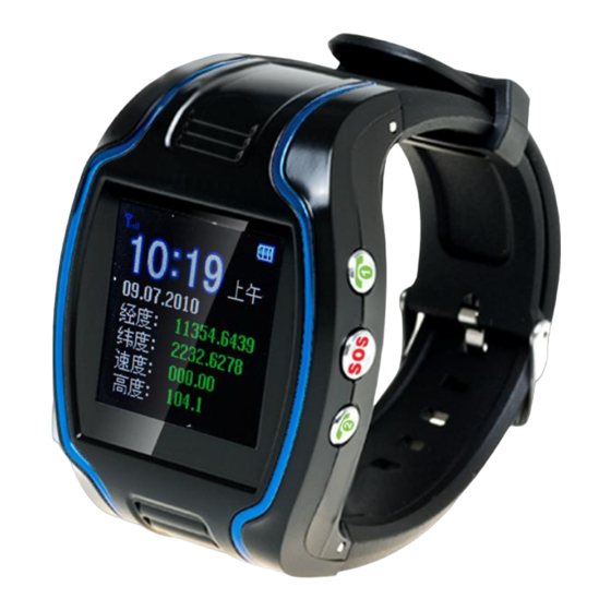
2. Interface Definition GSM signal strength is indicated on the upper left corner of the main interface as showed in picture 2: Bottom left button is for interface switch as showed in picture 3: III. Charge the Battery Please use up the battery and discharge it for 2-3 times and then charge the battery for at least 12 hours for initial use, in order to keep the quality of the battery. - Page 10 Put the battery into the inside of the terminal and connect the charger to 100V/220V AC power supply to charge the battery. Then the power indicator on the upper right corner of the terminal screen will keep strolling as showed in picture 3-1: ( picture 3-1 ) ...
-
Page 11: Iv.installation Of Sim Card
the battery may vary due to difference of internet service, functional mode and usage mode. Disconnect the terminal and charger as soon as possible after the battery is well charged. IV. Installation of SIM Card Open the back cover, then you will see the place where the SIM card is placed. -
Page 12: Location Inquiry
1. Location Inquiry (1) SMS Inquiry Create 988 + password command (defaulted password as 0000) via mobile phone and send it to the terminal mobile phone number; after successful sending, the guardian’s mobile phone will receive a piece of message. See the flow as follows: ①... -
Page 13: Platform Inquiry
the terminal will return a piece of detailed latitude and longitude message. (2) Platform Inquiry Step 1: Log onto the platform (Please contact with the service provider to get the platform address). Step 2: Click the terminal of the ward, then the location of the ward will be displayed on the map. -
Page 14: Bi-Directional Call Function
Note: All alarming information thereafter including SOS, low power, electronic fence, etc will be returned to that number. 3. Bi-directional Call Function Incoming calls can be rejected by pressing upper left button or received by pressing middle right button. Send the command in form of SMS to the terminal via mobile phone. After the setup is successful, the mobile phone will receive the “&710&successful setting&&”... -
Page 15: Sos Function
button to adjust receiver volume. 5. SOS Function If a ward number (predetermined number in item3) is set, when the ward encounters emergency and presses the SOS button, the terminal will send alarming information to the center number and dial the three ward numbers in turn. -
Page 16: Regular Upload Interval Setup
ward, then the ward terminal will automatically call back to the mobile phone of the guardian and the guardian may hear the sound of the surroundings within 10m around the ward. SMS format: 5550000 Remarks: 0000 is the initial defaulted password and in practice the password could be set by the user. -
Page 17: Function Of Changing Password
8. Function of Changing Password Send the SMS “#770# User new password # User old password ##” by mobile phone to the terminal number, after successful sending, the mobile phone with such setup will receive one piece of ‘&770&successful setting&&’ response information or ‘&770&PASSWORD ER&&’ if the password is wrong, as shown in the following picture: ①... -
Page 18: Set Server Address Command
GPRS mode is required to be set up according to actual demand. After the setup is successful, the terminal will send reply with ‘&801&successful setting&&’ or ‘&801&PASSWORD ER&&’ if the password is wrong. 10. Set APN Command Create the SMS “802#APN letters or digits, 4-20 bits # Log user name letters or digits 4-20 bits in # Log password letter or digits 4-20 bits in # terminal password 4 bits ##”... -
Page 19: Low Voltage Alarming Function
module will send a reply with ‘&803&successful setting&&’ or ‘&803&PASSWORD ER&&’ if the password is wrong. Example: #803#222.73.173.204#7003#0000## Setup via domain name: Example: #803#gps.chinaradio.hk#9876#0000## 12. Low-Voltage Alarming Function If the terminal of the ward has a very low power and needs to be powered off, the terminal of the ward will automatically upload one piece of low-voltage alarming command to the monitoring center number. -
Page 20: Electronic Fence Function
current time is 09:30:08, after sending the command 8960000E08, the time will add with 8 and change into 17:30:08. Similarly, when setting the command 8960000W07, the time will automatically reduce with 7 and change into 02:30:08. When satellite time is corrected to GMT automatically, send SMS command 8960000E08 and the time will change into Beijing time. -
Page 21: Function Of Canceling Fence
(2) Fence Reading Function Send commands to the terminal: # command number (752) # user password 4 digits ##; after the command is set successfully, the terminal will read the data of the module fence working status and return message to the sending mobile phone, or PASSWORD ER if the password is wrong. -
Page 22: Auxiliary Functions
(3) Function of Canceling Fence Command name: # command number (760) # user password 4-digits ## Example: #760#0000## After the terminal receiving this command, all fence settings will be cancelled. Advice: Do not set GSM fence and GPS fence at the same time. 15. - Page 23 5. This device supports the dual positioning mode of GPS and GSM/GPRS. 6. Please use this device in a legal area, any illegal consequence will be borne by the user. Notes: due to the high sensitivity of the GPS module adopted by this product, it is normal to be drifting with weak GPS signal.
Need help?
Do you have a question about the TK109 and is the answer not in the manual?
Questions and answers