Table of Contents
Advertisement
Quick Links
Advertisement
Table of Contents

Summary of Contents for EcLine EC-1559
- Page 1 POS Terminal EC-1559 Service Manual...
- Page 3 This device may not cause harmful interference, and This device must accept any interference received, including interference that may cause undesired operation. Korea Communications Commission (KCC) KCC-REM-PTP-EC-1559 A급 기기 (업무용 방송통신기자재) 이 기기는 업무용(A급) 전자파적합기기로서 판매자 또는 사용자는 이 점을 주의하시기 바라며, 가정외의 지...
- Page 4 About this manual The service manual provides service information for the EC-1559. This manual is designed to help train service personnel to locate and fix failing parts on the machine. This manual consists of the following sections: Chapter 1 Getting Started: This section covers unpacking and checking the package contents, and identifying components.
-
Page 5: Table Of Contents
TABLE OF CONTENTS CHAPTER 1 GETTING STARTED ..........1 Unpacking the machine .................1 Identifying components .................2 CHAPTER 2 BIOS SETUP ............5 About the Setup Utility ...................5 Entering the Setup Utility ................6 BIOS navigation keys ................6 Using BIOS ....................7 Main Screen ....................8 Advanced Settings ..................9 ACPI Settings ..................10 CPU Configuration ...................11... - Page 6 CHAPTER 4 LOCATING THE PROBLEM ......... 43 General checkout guidelines ................43 Cash drawer checkout .................43 LCD symptoms .....................44 Touch screen symptoms ................45 Power symptoms..................45 Network symptoms ..................45 USB symptoms ....................46 Peripheral-device symptoms ................46 Boot symptoms ....................46 Mainboard jumper ..................47 Mainboard connectors..................49 Inverter connectors ..................49 CHAPTER 5 REPLACING FIELD REPLACEABLE UNITS (FRUs) .....................
- Page 7 Figure 1.1 Unpacking the machine ............1 Figure 1.2 Front-right view ..............2 Figure 1.3 Rear view ................3 Figure 1.4 EC-1559 I/O connectors ............4 Figure 2.1 Main BIOS screen ..............6 Figure 2.2 Main Screen ................8 Figure 2.3 Advanced Settings Screen ............. 9 Figure 2.4 ACPI Settings sub-menu ............
-
Page 9: Chapter 1 Getting Started
CHAPTER 1 GETTING STARTED This chapter describes how to unpack and identifying components on the device. The following topics are described. • Unpacking the machine on page 1 • Identifying components on page 2 Unpacking the machine It is a good idea to save the packaging materials and shipping box in case that machine needs to be returned for service. -
Page 10: Identifying Components
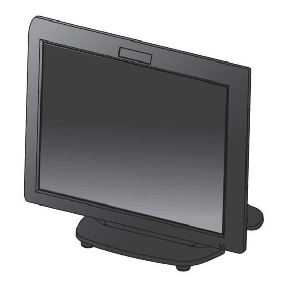
Identifying components This section describes the parts and connectors on the machine. Front-right view Figure 1.2 Front-right view Component Description 15-inch TFT LCD LED Power Indicator/ HDD Indicator IO Panel Cover IO Panel Power Button C H A P T E R 1 G E T T I N G S T A R T E D... -
Page 11: Figure 1.3 Rear View
Rear view Figure 1.3 Rear view Component Description MSR (optional) Slot VFD Customer Display (optional) Slot Cable Compartment HDD Compartment Cable Compartment Cover... -
Page 12: Figure 1.4 Ec-1559 I/O Connectors
I/O connectors Figure 1.4 EC-1559 I/O connectors Connector Description COM 4 port VGA port COM 1 port USB ports RJ-11 cash drawer port DC 12V input connector PS/2 port COM 3 port COM 2 port LAN jack Parallel port DC 12V output connector (for 2nd LCD Monitor) -
Page 13: Chapter 2 Bios Setup
CHAPTER 2 BIOS SETUP The primary function of the BIOS (Basic Input and Output System) is to identify and initiate component hardware. The BIOS parameters are stored in non-volatile BIOS memory (CMOS). CMOS contents don’t get erased when the computer is turned off. The following topics are described in this chapter. •... -
Page 14: Entering The Setup Utility
Entering the Setup Utility When you power on the system, BIOS enters the Power-On Self Test (POST) routines. POST is a series of built-in diagnostics performed by the BIOS. After the POST routines are completed, the following message appears: Press DEL to run Setup Press the delete key <Delete>... -
Page 15: Using Bios
Using BIOS When you start the Setup Utility, the main screen appears. The main screen of the Setup Utility displays a list of the options that are available. A highlight indicates which option is currently selected. Use the cursor arrow keys to move the highlight to other options. -
Page 16: Main Screen
Main Screen This screen includes System BIOS Information, Processor, System memory and displays the System Time and System Date. Figure 2.2 Main Screen System Overview This screen displays System BIOS Information, Processor, System memory, System Time and System Date. System Time/ System Date The System Time and System Date items show the current date and time held by the machine. -
Page 17: Advanced Settings
Advanced Settings This setup screen includes sub-menus for APCI Configuration, CPU Configuration, SATA Configuration, USB Configurations, Super IO Configurations and Hardware Health Configuration. Figure 2.3 Advanced Settings Screen... -
Page 18: Acpi Settings
ACPI Settings Figure 2.4 ACPI Settings sub-menu Enable Hibernation This item allows user to enable or disable the hibernation feature for OS. This option may be not effective with some OS. ACPI Sleep State Use this item to define how the system suspends. In the default, S1 only (CPU Stop Clock), the suspend mode is equivalent to a software power down. -
Page 19: Cpu Configuration
CPU Configuration Figure 2.5 CPU Configuration sub-menu Active Processor Cores This feature allows you to increase or decrease the number of active processor cores. Limit CPUID Maximum When enabled, the processor will limit the maximum CPUID input value to 03h when queried, even if the processor supports a higher CPUID input value. -
Page 20: Sata Configuration
SATA Configuration Figure 2.6 SATA Configuration sub-menu SATA Controller(s) Use this item to enable or disable the on-chip SATA controller. The default setting is Enabled. SATA Mode Selection This item is used to configure SATA mode. The default setting is IDE. IDE Legacy / Native Mode Selection This item allows you to select IDE mode. -
Page 21: Usb Configuration
USB Configuration Figure 2.7 USB Configuration sub-menu Legacy USB Support When enabled, the BIOS will enable legacy support for USB keyboards, mice and floppy drives. You will be able to use these USB devices even with operating systems that do not support USB. EHCI Hand-Off This item allows you to enable support for operating systems without an EHCI hand-off feature. -
Page 22: Super Io Configuration
Super IO Configuration Figure 2.8 Super IO Configuration sub-menu Serial Port x Voltage select This item allows you to set voltage for a serial port. Watch Dog Degree This item allows you to determine the functional degree of Watch Dog. Watch Dog Timer When select any time period, the Watchdog Timer will be enabled after that time period passes, every time the system boots up. -
Page 23: Serial Port X Configuration
Serial Port x Configuration Figure 2.9 Serial Port x Configuration sub-menu Serial Port x This item allows you to enables or disables a serial port. Change Settings This item allows you to specific IO address and IRQ for the serial port. -
Page 24: Parallel Port Configuration
Parallel Port Configuration Figure 2.10 Parallel Port Configuration sub-menu Parallel Port This item allows you to enables or disables the parallel port. Change Settings This item allows you to specific IO address and IRQ for the parallel port. Device Mode This item allows you to set the data transfer protocol for the parallel port. -
Page 25: H/W Monitor
H/W Monitor Figure 2.11 Hardware Monitor sub-menu Shutdown Temperature This item allows setting the shutdown temperature. Once enabled, the machine will automatically shutdown when the temperature reaches the limit specified. -
Page 26: Cpu Ppm Configuration
CPU PPM Configuration Figure 2.12 CPU PPM Configuration sub-menu EIST This item allow you to enable or disable EIST (Enhanced Intel Speedstep Technology). When enabled, CPU will reduce power consumption. CPU C3 Report This item is used to enable or disable CPU C3 report to OS. CPU C6 Report This item is used to enable or disable CPU C6 report to OS. -
Page 27: Chipset Settings
Chipset Settings This screen allow you to configure the chipset options. Figure 2.13 Chipset Settings Screen System Agent (SA) Configuration Figure 2.14 System Agent (SA) Configuration sub- menu... -
Page 28: Pch Io Configuration
PCH IO Configuration Figure 2.15 PCH IO Configuration sub-menu Onboard LAN Use this item to enable or disable the onboard LAN controller. The default setting is Enabled. Onboard LAN OPROM This feature allows you to enable or disable the onboard LAN boot ROM to boot system. Mini PCI Express Port This item allows you to enable or disable the Mini PCI Express device. -
Page 29: Usb Configuration
USB Configuration Figure 2.16 USB Configuration sub-menu EHCI1, EHCI2 These item allow you to enable or disable USB 2.0 support. -
Page 30: Graphics Configuration
Graphics Configuration Figure 2.17 Graphics Configuration sub-menu GTT Size This field allows you to select how much system memory can be allocated to GTT. Aperture Size This field allows you to select how much system memory can be allocated to graphics chip for video purposes. - Page 31 Panel Scaling This item allows you to determine how various resolutions appear on your screen. Option Description The scaling unit on your graphics card will rescale the image before it reaches your LCD Auto display. This option results in the best image quality. The image isn’t scaled at all, but instead your LCD display will run at its maximum resolution and the image will display in the centre of your LCD display.
-
Page 32: Memory Configuration
Memory Configuration Figure 2.18 Memory Configuration sub-menu Memory Frequency Limiter This item allows you to set the maximum frequency of system memory. Max TOLUD This field allows you to select the maximum value of TOLUD. Dynamic assignment would adjust TOLUD automatically based on largest MMIO length of installed graphic controller. -
Page 33: Boot Settings
Boot Settings This screen allow you to configure the boot options. Figure 2.19 Boot Settings Screen Setup Prompt Timeout This item allows you to select the number of seconds to wait for setup activation key. Bootup Numlock State This item is used to select the Power-on state for Numlock. Full Logo Screen display This item enables you to show the full screen logo on the bootup screen. -
Page 34: Security Settings
Security Settings This screen allows you to configure the system security settings. Figure 2.20 Security Settings Screen Create or Change Adminitrator/ User Password An administrator password takes precedence over a user password, and the administrator can limit the activities of a user. To create or change a password, follow these steps: 1. -
Page 35: Save & Exit
Save & Exit This screen allows you to load default setting values, save changes and discard changes. Figure 2.21 Save & Exit Screen Discard Changes and Exit Highlight this item and press <Enter> to discard any changes that you have made in the Setup Utility and exit. When the dialog box appears, press <Yes>... - Page 36 C H A P T E R 2 B I O S S E T U P...
-
Page 37: Chapter 3 Installing Drivers And Software
Use an external CD-ROM drive to install the drivers or copy the drivers to a USB flash drive and then plug to the machine. When you insert the CD ROM the following screen appears. Check EC-1559 that is listed under the “Install Terminal Drivers” and “Install Device Drivers” menus. -
Page 38: Intel Chipset Driver
Intel Chipset Driver The Intel Chipset Device Software updates the Windows XP/7 INF files so that the Intel chipset is correctly configured. Follow these instructions to install the chipset software : 1. Browse to the \DRIVER\chipset\Intel\Inf folder. 2. Double-click setup.exe. The following screen appears. Click Next to continue. 3. - Page 39 4. Browse the ReadMe Information, then click Next. 5. The Intel Chipset Software Utility files are installed to the system. When prompted to restart, select Yes, I want to restart my computer now. Then click Finish to restart the system.
-
Page 40: Intel Chipset Graphics Driver
Intel Chipset Graphics Driver This utility installs the Intel Extreme Graphics 2 drivers for Windows XP/2000. To install the drivers. 1. Browse to the \DRIVER\VGA\intel\ folder. 2. Double-click the executable file. The following screen appears. Click Next to continue. 3. Read the license agreement, then click Yes. C H A P T E R 3 I N S T A L L I N G D R I V E R S A N D S O F T W A R E... - Page 41 4. Browse the ReadMe Information, then click Next. 5. When installation is completed, select Yes, I want to restart my computer now. Then click Finish to restart the system.
-
Page 42: Lan Driver
LAN Driver The network driver support Windows XP/2000. Refer to the following to install the drivers. 1. Browse to the \DRIVER\LAN\RealTek folder. 2. Double-click the executable file. The following screen appears. Click Next to continue. 3. Click Install to begin installation. C H A P T E R 3 I N S T A L L I N G D R I V E R S A N D S O F T W A R E... - Page 43 4. When installation is completed, click Finish.
-
Page 44: Touch Screen Driver
Touch Screen Driver Refer to the following to install the touch screen driver. 1. Browse to the \DRIVER\Touch\eGalax folder. 2. Double-click setup.exe. The following screen appears. Click Next to continue. 3. Read the license agreement, check “I accept the term of the license agreement”. Click Next to continue. - Page 45 4. Check the box for Install PS/2 interface drive and then click Next to continue. 5. System will give you a warning, click OK to continue. 6. Uncheck the box for Install RS232 interface drive and then click Next to continue.
- Page 46 7. Check the box for None and then click Next to continue. 8. System will give you a warning, click OK to continue. 9. Uncheck the box for Support Mulit-Monitor System and then click Next to continue. C H A P T E R 3 I N S T A L L I N G D R I V E R S A N D S O F T W A R E...
- Page 47 10. Click Next to continue. 11. Click Next to continue.
- Page 48 12. Click Next to continue. 13. Click Yes, I want to restart my computer now and then click Finish. C H A P T E R 3 I N S T A L L I N G D R I V E R S A N D S O F T W A R E...
-
Page 49: Calibrating The Touchscreen
Calibrating the touchscreen Follow these instructions to calibrate the touchscreen using the TouchKit application: 1. Launch the TouchKit application from the Windows desktop by clicking on Start > All Programs > eGalaxTouch > Configure Utility. 2. Select the Tools page. 3. - Page 50 5. Click OK to complete the 4 points calibration. You may also use this application to adjust the touch settings. NOTE C H A P T E R 3 I N S T A L L I N G D R I V E R S A N D S O F T W A R E...
-
Page 51: Chapter 4 Locating The Problem
CHAPTER 4 LOCATING THE PROBLEM Refer to this section to locate the problem with the machine. The following topics are described. • General checkout guidelines on the page 43 • Cash drawer checkout on the page 43 • LCD symptoms on the page 44 •... -
Page 52: Lcd Symptoms
Figure 4.1 Connecting a cash drawer Cashdrawer 2. Turn on the machine . Refer to the following to prevent incorrect cash drawer status detection by the system: Port I/O Port Address Condition Note Cashdrawer A High(1) → Close If Bit is set to Low to open the Control port cash drawer, after it must be set Low(0) →... -
Page 53: Touch Screen Symptoms
Touch screen symptoms Symptom Corrective Procedure • Touchscreen does not 1. Install and run the touchscreen calibration program from the driver function • No virtual mouse 2. Reseat the panel cable. • Cursor doesn’t follow when 3. Reseat the touchscreen board-to-touch panel cable. touching the screen 4. -
Page 54: Usb Symptoms
USB symptoms Symptom Corrective Procedure • USB device does not function 1. Check that the USB device is detected in Windows Device Manager. 2. Reinstall the USB device driver. 3. Replace the mainboard. Peripheral-device symptoms Symptom Corrective Procedure • USB ports do not work 1. -
Page 55: Mainboard Jumper
Mainboard jumper JLV1 JLV2 JLV3 Figure 4.2 EC-1559 mainboard jumper JCMOS1 Jumper Setting Description 1-2 Closed JLV1 (LCD Backlight Inverter Power Select Jumper) 2-3 Closed 1-2 Closed 3.3V JLV2 (LCD Panel Power Select Jumper) 2-3 Closed 1-2 Closed Voltage Level Mode... - Page 56 Jumper Setting Description 1-2 Close 3-4 Close RING (COM3 Power Select Jumper) 5-6 Close 1-2 Close 3-4 Close RING (COM4 Power Select Jumper) 5-6 Close 1-2 Close Keep Data JCMOS1 (Clear CMOS Jumper) 2-3 Close Clear CMOS 1-2 Close (CN2 USB Power Select Jumper) 2-3 Close 3.3V C H A P T E R 4 L O C A T I N G T H E P R O B L E M...
-
Page 57: Mainboard Connectors
LED connector to connector to speaker power jack connector to touch panel connector to connector to PS/2 port parallel port Figure 4.3 EC-1559 mainboard connectors Inverter connectors connector to mainboard connector to connector to Figure 4.4 Inverter connectors... - Page 58 C H A P T E R 4 L O C A T I N G T H E P R O B L E M...
-
Page 59: Chapter 5 Replacing Field Replaceable Units (Frus)
After replacing optional devices, make sure all screws, springs, or other small parts are in place and are not left loose inside the case. Metallic parts or metal flakes can cause electrical shorts. Only qualified personnel should perform repairs on the EC-1559. Damage due to unauthorized servicing is not covered by the warranty. -
Page 60: Before You Begin
CAUTION Before you begin Make sure you have a stable, clean working environment. Dust and dirt can get into the EC-1559 components and may cause malfunction. Adequate lighting and proper tools can prevent you from accidentally damaging the internal components. Most of the electrical and mechanical connections can be disconnected by using your fingers. -
Page 61: Hdd
Refer to the following to remove and replace the hard drive. 1. Turn off the device properly through the operating system. 2. Disconnect the power cord from the power outlet. 3. Remove the screw form the hard drive compartment cover and slide the cover to the right as it shown on the picture. -
Page 62: Io Panel Cover
IO Panel Cover 1. Flip up the LCD panel 2. Remove two screws from the IO panel cover and remove the cover. Stand Base Back Cover 1. Rotate the LCD forward to the end. 2. Remove the stand base back cover. -
Page 63: Stand Base
Stand Base Before proceeding, remove the fol- lowing FRUs. • “IO Panel Cover” on page 54. 1. Flip up the LCD panel 2. Remove the screw from the IO panel. 3. Position the EC-1559 as shown. 4. Remove the stand base. -
Page 64: Back Cover
Back Cover 1. Remove the screw from VFD slot cover. 2. Remove the VFD slot cover. 3. Remove all screws from the back cover. 4. Remove the back cover. C H A P T E R 5 R E P L A C I N G F I E L D R E P L A C E A B L E U N I T S ( F R U s ) -
Page 65: Speaker
To avoid the thermal issue. When you replace the back cover, check the thermal pads should be complete and stuck on the CPU and chip. If the thermal pads damaged, replace them. CAUTION When replace the back cover, the two standoff screws must be installed as shown below. -
Page 66: Power Button
Power Button Before proceeding, remove the following FRUs. • “Back Cover” on page 56. 1. Remove two screws. 2. Remove the power button. COM4 port and PS/2 Port Before proceeding, remove the following FRUs. • “Back Cover” on page 56. 1. -
Page 67: I/O Shield
I/O Shield Before proceeding, remove the following FRUs. • “Back Cover” on page 56. • “COM4 port and PS/2 port” on page 58. 1. Remove all screws from the I/O panel. 2. Remove four screws from the I/O shield. 3. Remove the I/O shield. Memory Before proceeding, remove the following FRUs. -
Page 68: Battery
Battery Before proceeding, remove the following FRUs. • “Back Cover” on page 56. 1. Open the hock. 2. Pull out the battery. Mainboard Before proceeding, remove the following FRUs. • “Back Cover” on page 56. • “COM4 port and PS/2 port” on page 58. -
Page 69: Inverter
Inverter Before proceeding, remove the following FRUs. • “Back Cover” on page 56. 1. Remove five screws. 2. Remove the inverter cover. 3. Remove three screws. 4. Remove all cables from the inverter. 5. Remove the inverter. When replacing: Put the inverter in the plastic cover before replacing it. -
Page 70: Panel Bracket
Panel Bracket Before proceeding, remove the following FRUs. • “Back Cover” on page 56. • “Speaker” on page 65. • “Power Button” on page 66. • “COM4 port and PS/2 port” on page 58. • “I/O Shield” on page 59. •... -
Page 71: Appendix Part List And Specification
APPENDIX PART LIST AND SPECIFICATION Figure 6.1 Exploded diagram main parts... -
Page 72: Figure 6.2 Exploded Peripheral Parts
Figure 6.2 Exploded peripheral parts A P P E N D I X... -
Page 73: Part List
Part list (*) is option DESCRIPTION ITEM NO DESCRIPTION ITEM NO Front Cover AL 2100050470001 Hinge right 2108100000024 Waterproof seal 25005500B0004 Stand base AL 2100250470000 HT Tocuh/15” 2619040300007 Foot 2509030503011 Touch Holder 25003500B0002 Cable 1721209110009 TFT LCD/15” 2614550150104 Cable 1721211090009 MB Bracket 26105500S5300 DC Jack Cable... -
Page 74: Specifications
Specifications Item EC-1559 CPU Type Intel Processor Celeron 1.8 GHz dual core fanless design ® ® Chipset Intel chipset 15” LCD, resolution 1024 x 768 LED backlight ELO 5-wire resistive touch screen, ELO Touch control board(RS-232 Touch interface) Memory 2GB RAM...
Need help?
Do you have a question about the EC-1559 and is the answer not in the manual?
Questions and answers