Table of Contents
Advertisement
Quick Links
Advertisement
Table of Contents

Related Manuals for ooznest OX CNC

Summary of Contents for ooznest OX CNC
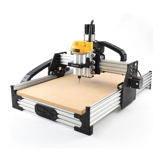
- Page 1 OX CNC Assembly Instructions OX CNC...
-
Page 2: Table Of Contents
2.6.7 Spoiler Board Support - 2 ............31 2.6.8 End-Caps ................. 32 GT3-Pulley & Belt Assembly 2.7.2 Tee-Nuts.................. 34 2.7.3 GT3-Timing-Belt ............... 35 2.7.4 Securing the GT3-Timing-Belt ............. 36 2.7.5 Repeat ..................37 Face-Plate Complete Appendix Appendix A - Kit Contents OX CNC... - Page 3 1.0 Getting Started OX CNC Getting Started...
-
Page 4: About The Kit
1.1 About The Kit The ooznest OX CNC Machine Kit is based on the OX CNC Machine designed by Mark Carew of Openbuilds (http://www.openbuilds.com/builds/openbuilds-ox-cnc-machine.341/), and in- corporates many upgrades from the Openbuilds community. Mark Carew based the OX on the Routy, which was in turn based on the Shapeoko. - Page 5 Simply place them in the V-Slot, then screw in the bolt which will turn them and engage them into the underside of the V-Slot. OX CNC Getting Started...
-
Page 6: Assembly
2.0 Assembly OX CNC Assembly... -
Page 7: Wheel Assembly
2.1 Wheel Assembly A. With a Precision-Shim in between, insert a 625-2RS-Bearing into either side of the Solid- V-Wheel-Xtreme. B. Repeat this for all 30 Solid-V-Wheel-Xtremes. OX CNC Assembly... -
Page 8: Side Plates
Plate (the straight vertical side). B. Only loosely tighten the bolts for now. These will be tightened later once the GT3-Belt has been attached. Make sure the M5-Low-Profile-20mm Bolts are sitting on the bottom sur- face of the elongated holes. OX CNC Assembly... -
Page 9: Wheel & Brace Assembly
There should be a small amount of friction. Make sure that, when adjusting the Eccentric-Spacers, the divots on each side of the wheel are kept in- line– i.e whatever is done to one side of wheel should be done to the other. OX CNC Assembly... - Page 10 20x80mm V-Slot still runs smoothly. 2.2.3 Repeat A. Repeat Section 2.2 for the other Y-Plate. However, this time it should be a mirror image of the first Y-Plate, as shown in the image above. OX CNC Assembly...
-
Page 11: X-Carriage Assembly
2.3.1 Front Plate Spacer Blocks A. Attach one Spacer-Block to the X-Plate-Front using 2 x M5-Low-Profile-10mm’s. The bot- tom of the Spacer-Block should be flush with the bottom for X-Plate-Front. B. Repeat Step A for the second Spacer-Block. OX CNC Assembly... -
Page 12: Front Plate Wheel Assembly Part 1
Block. The wheel can be tightened down, but leave it slightly loose and initially set the Eccentric-Spacer so the divot on the side is facing right. C. Repeat Step A for the other 2 wheels on the left row, and repeat Step B for the other 2 wheels on the right row. OX CNC Assembly... -
Page 13: Front Plate Wheel Assembly Part 2
D. Once you’re satisfied, the right row of wheels can be tightened down. Once tight, recheck that the 20x60mm V-Slot still runs smoothly. E. Attach the ACME-Nut-Block to the X-Plate-Front. The M5-Nyloc-Nuts go into the insets and should be facing away from the X-Plate-Front. OX CNC Assembly... -
Page 14: Attaching Back Plate Motor
B. Only loosely tighten the bolts for now. These will be tightened later once the GT3-Belt has been attached. Make sure the M5-Low-Profile-20mm Bolts are sitting on the bottom sur- face of the elongated holes. OX CNC Assembly... -
Page 15: Mating Front & Back Plates
View. Doing this maximizes the gap between the top and bottom row of wheels. E. Simultaneously, run 2 pieces of 20x60mm V-Slot Extrusion in between the two rows of wheels on both sides. Initially the V-Slot should wobble in between the wheels. Push the OX CNC Assembly... - Page 16 F. Once satisfied, the bottom row of wheels can be tightened down. Once tight, recheck that 2 x 20x60mm V-Slot still runs smoothly. OX CNC Assembly...
-
Page 17: Z Axis Assembly
A. Slide the 1/4” side (the side with the smallest hole) of the Flexible-Coupler onto the shaft of the NEMA23-Stepper-Motor. Don’t tighten it down at this point. B. Then attach the NEMA23-Stepper-Motor to the Threaded-Rod-Mount-Motor. Make sure the inset for the 688ZZ-Bearing is facing away from the NEMA23-Stepper-Motor. OX CNC Assembly... -
Page 18: Attaching V-Slot
A. Attach the V-Slot-2060-200mm to the Threaded-Rod-Mount-Motor using 3 x M5-Low-Pro- file-10mm. For the middle bolt, the short end of the Allen key may need to be used. Leave these bolts initially loose so the Threaded-Rod-Motor-Mount can be adjusted forward and backwards. OX CNC Assembly... -
Page 19: Attaching Acme-Lead-Screw
Rod-Mount-Motor. If it isn’t, the Threaded-Rod-Mount-Motor can be moved up or down by turning the ACME-Lead-Screw in the appropriate direction. E. Once they are touching, make sure the back edge of the Threaded-Rod-Mount-Motor is square with the V-Slot-2060-200mm, and tighten the M5-Low-Profile-10mm bolts attached in the previous section. OX CNC Assembly... -
Page 20: Threaded-Rod-Mount-Bottom
8mm-Lock-Collar on top. E. The Flexible-Coupler can now be locked in place. Make sure one of the grub screws is on the flat section of the shaft on the NEMA23-Stepper-Motor and that the ACME-Lead-Screw and motor shaft are touching. OX CNC Assembly... -
Page 21: Gantry Assembly
Tighten the screws down, and when doing so, make sure you squeeze and push both rails to the back so the screws on the back rail are touching the back of their respective slots. Also keep the top of the rails flush with each other. Tighten all 6 bolts holding the rails. OX CNC Assembly... -
Page 22: Tee-Nuts & Carriage
E. Slide the X-Carriage along the gantry to make sure it runs smoothly. If it doesn’t run smoothly, recheck the Eccentric-Spacers. If the Eccentric-Spacers are correct and it still doesn’t run smoothly, loosen the bolts holding the 2 x V-Slot-2060-500mm’s and readjust the rails. OX CNC Assembly... -
Page 23: Angle-Corners
Low-Profile-15mm goes though the Angle-Corner and attaches to a M5-Nyloc-Nut on the Y-Plate side. B. Repeat Step A for the other 4 Angle-Corners on the Y-Plate-Right in the positions shown above. Repeat again for the 5 Angle-Corners on the Y-Plate-Left in the same positions. OX CNC Assembly... -
Page 24: Base Assembly
B. Rest the ends of the V-Slot-2080-750mm’s on top of a V-Slot-2040-494mm rail at each end. This is shown in the picture above. The ends of the V-Slot-2040-494mm’s should be flush with the side of the V-Slot-2080-750mm’s OX CNC Assembly... -
Page 25: Y-End-Plates
F. Slide the X-Gantry to the back. Square the base, and repeat Steps A,B,C & D for the back two Y-End-Plates. Again, if possible, get a second person to hold the base square while tightening the bolts. OX CNC Assembly... -
Page 26: V-Slot Positioning - 2
B. Insert the V-Slot-2040-454mm in between both V-Slot-2080-750mm’s so it sits on top of the front V-Slot-2040-494mm. The outward face should be against the Y-End-Plates. C. Repeat Steps A & B for the back V-Slot-2040-454mm. There is no need to insert the two extra Tee-Nuts. OX CNC Assembly... -
Page 27: Y-End-Plates - Final Bolts
C. Repeat Steps A & B for the other 3 Y-End-Plates. Again, If possible, get a second person to hold the base square while tightening the bolts. OX CNC Assembly... -
Page 28: Angle-Corners
If one side is maxing out before the other then the base needs re-adjusting, do this by slightly un-tightening the bolts on the Y-End-Plates and then pull the base in the right way to square it, then re-tighten the bolts. OX CNC Assembly... -
Page 29: Spoiler Board Support - 1
V-Slot-2080-710mm. With the top of the Universal-Bracket-Triple flush with the top of the V-Slot-2080-710mm, secure it using 3 x M5-Low-Profile-8mm’s. C. 3 more Universal-Brackets-Triple need to be attached to the V-Slot-2080-710mm as shown above, repeating Steps A & B. OX CNC Assembly... -
Page 30: Spoiler Board Support - 2
Universal-Bracket-Triple towards the top, and line up the center of the V- Slot-2080-710mm with the center marks made in Step B. D. Line up all the previously inserted Tee-Nuts with the holes on the Universal-L-Brackets- Triple, and secure the spoiler board support using 12 x M5-Low-Profile-8mm’s. OX CNC Assembly... -
Page 31: End-Caps
2.6.8 End-Caps A. Attach an End-Cap to the left end of the front V-Slot-2040-494mm using 2 x M5-Low-Pro- file-8mm’s. B. Repeat Step A for the other 3 bare ends of the V-Slot-2040-494mm rails. OX CNC Assembly... -
Page 32: Gt3-Pulley & Belt Assembly
GT3-Pulley so the centre of the toothed section is aligned with the centre of the V- Slot-2080-750mm and so one of the grub screws will be against the flat section of the motor shaft. Secure it using the two grub screws provided. OX CNC Assembly... -
Page 33: Tee-Nuts
2.7.2 Tee-Nuts A. Slide a Tee-Nut, flat face down, through the slot on the back right Y-End-Plate and into the top slot of the V-Slot-2080-750mm. B. Repeat Step A for the front end of the same V-Slot-2080-750mm. OX CNC Assembly... -
Page 34: Gt3-Timing-Belt
B. Currently, the NEMA23-Stepper-Motor should be loosely sitting on the bottom surface of it’s slots. Lift the NEMA23-Stepper-Motor up just over halfway up it’s slots, and tighten the 4 x M5-Low-Profile-20mm bolts holding it. If you can’t access the bolts, lift it up higher as needed. OX CNC Assembly... -
Page 35: Securing The Gt3-Timing-Belt
Low-Profile-8mm bolt, pull the end of the Y-GT3-Timing-Belt to tension it. C. Slide the X-Gantry back and fourth a couple of times, and while doing so, check that the Y-GT3-Timing-Belt does not rub against the side of the GT3-Pulley. If it does, adjust the GT3-Pulley as needed. OX CNC Assembly... -
Page 36: Repeat
A. Repeat Section 2.7 for the left Y-Axis V-Slot-2080-750mm. Try to keep it consistent so whatever was done on the right side is repeated on the left. B. Repeat Section 2.7 for the back X-Axis V-Slot-2060-500mm, but this time use the X-GT3- Timing-Belt. OX CNC Assembly... -
Page 37: Face-Plate
2.8 Face-Plate A. Attach the Face-Plate using 4 x M5-Low-Profile-6mm’s to the already inserted Tee-Nuts on the front V-Slot-2040-494mm & V-Slot-2040-454mm. OX CNC Assembly... -
Page 38: Complete
2.9 Complete Congratulations you have completed the ooznest OX Assembly. We hope you have enjoyed the build and will continue from here and bring your OX to life! OX CNC Assembly... -
Page 39: Appendix
3.0 Appendix OX CNC Appendix... -
Page 40: Appendix A - Kit Contents
3.1 Appendix A - Kit Contents Plates 2 x Y-Plate 2 x Y-Brace 1 x X-Plate-Front 1 x Threaded-Rod- Mount-Motor 1 x X-Plate-Back 1 x Threaded-Rod- Mount-Bottom 4 x Y-End-Plates 1 x Face-Plate 4 x End-Caps OX CNC Appendix... - Page 41 V-Slot Rails 2 x V-Slot-2040- 1 x V-Slot-2060- 454mm 200mm 2 x V-Slot-2040- 2 x V-Slot-2060- 494mm 500mm 1 x V-Slot-2040- 500mm 1 x V-Slot-2080- 710mm 2 x V-Slot-2080- 750mm OX CNC Appendix...
- Page 42 Motion Components 30 x Solid-V-Wheel- 60 x 625-2RS-Bear- Xtreme 1 x ACME-Lead- 1 x ACME-Nut-Block Screw 2 x 688ZZ-Bearing 1 x Flexible-Coupler 3 x GT3-Pulley 2 x Y-GT3-Timing- Belt 1 x X-GT3-Timing- Belt OX CNC Appendix...
- Page 43 Brackets & Spacers 14 x Angle-Corner 4 x Universal- Bracket-Triple 2 x Spacer-Block 20 x Eccentric- Spacer 12 x Aluminium- 86 x Precision-Shim Spacer-Eighth-Inch 8 x Aluminium- Spacer-6mm 24 x Aluminium- Spacer-Quarter-Inch 3 x Aluminium- Spacer-Onehalf-Inch OX CNC Appendix...
- Page 44 53 x M5-Nyloc-Nut M5-Low-Profile: 4 x 6mm 84 x 8mm 34 x 10mm 10 x 15mm 14 x 20mm 14 x 40mm 8 x 45mm 3 x 55mm 4 x 65mm 4 x NEMA23-Step- 5 x M5-Drop-In-Tee- per-Motor Nuts OX CNC Appendix...
Need help?
Do you have a question about the OX CNC and is the answer not in the manual?
Questions and answers