
Related Manuals for M&G DuraVent DIS

Summary of Contents for M&G DuraVent DIS
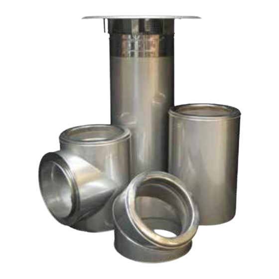
- Page 1 Installation Instructions A modular double-wall positive pressure chimney. Boiler Breeching and Stack Engine Exhaust. Grease Duct (DIS only)
- Page 2 A MAJOR CAUSE OF VENT RELATED FIRES IS FAILURE TO MAINTAIN REQUIRED CLEARANCES (AIR SPACES) TO COMBUSTIBLE MATERIALS. IT IS OF THE UTMOST IMPORTANCE THAT POLYPRO® BE INSTALLED ONLY IN ACCORDANCE WITH THESE INSTRUCTIONS. Important WarnIng CarBon monoXIDE poISonIng Read through all of these instructions HaZarD.
-
Page 3: Table Of Contents
Double Wall Construction positive pressure Chimney System For the most up-to-date installation instructions, see www.duravent.com CONTENTS IntroDuCtIon............4 tEStIng/LIStIng InFormatIon . -
Page 4: Introduction
SECtIon a - gEnEraL InFormatIon IntroDuCtIon DuraVent Model DuraStack DIS or DAS These instructions comprise both general Chimney are cylindrical, prefabricated, guidelines and special requirements for all parts in the product line. Before specifying a modular venting systems incorporating a unique extended inner flange designed for design or beginning an installation please both quick assembly and pressure sealing... - Page 5 SurrounDIngS / EnCLoSurE Building Heating Appliance Chimneys are suitable for use with Building Heating DuraVent models DIS and DAS chimney are Appliances and Low Heat Appliances as primarily intended to be used in fire resistive described in the Chimney Selection Chart of noncombustible surroundings or installed National Fire Protection Association (NFPA) unenclosed.
- Page 6 SyStEm SIZIng may be located in a corner formed by two walls of combustible construction, if the Complete system sizing and capacity conditions above are met. information maybe obtained from the 3. Other interior installations in all buildings “Chimney, Gas Vent, and Fireplace Systems” should be as follows: chapter of the ASHRAE Handbook (go to a) Where a grease duct penetrates a wall or...
- Page 7 EFFECtIVE LEngtH Table 3 When assembling two parts together, the DIS Minimum Openings joint will overlap 5/8”. So effective length is nominal length minus 5/8”. Model Roof / Floor (C) Wall (C) Effective Length Ø5" - Ø10" Inside Ø + 8" Inside Ø...
- Page 8 CHImnEy anD FIttIng JoInt aSSEmBLy All components have a male and female end. The installation orientation is indicated on the labeling of each chimney section with an arrow. The arrow indicates the direction of the flow. Clean all inner and outer surfaces of the male and female ends with an appropriate organic solvent, such as acetone, Mek, or other commercial degreaser.
- Page 9 Table 5 CautIon Sealant Usage DO NOT ALLOW SCREWS TO PENETRATE THE INNER FLUE. THIS CAN CAUSE Interior Installation CORROSION, GAS LEAKAGE OR EXPANSION Sealant Max. FAILURE. NEVER USE SCREWS THROUGH Supplier Model Color Application Temp. THE OUTER CASING OF AN ADJUSTABLE LENGTH OR EXPANSION JOINT.
- Page 10 Support mEtHoDS anD HEIgHt LImItS Table 7 1. Several support and guiding methods are Support and Guide Spacing for Model used to anchor a chimney against upward, DIS and DAS (dimensions in feet) downward and angular displacement. 2. These supports and guides used with MVS* Inside Diameter thermal expansion devices, prevent bending...
- Page 11 CHImnEy guyIng anD BraCIng away from the locking band. It is essential 1. Proper guying and bracing is essential that these parts be properly installed and for part of the chimney that extends above provided with adequate support and the roof or parapet wall. The chimney at this guidance to prevent binding or excessive bending forces.
-
Page 12: Section B: Tees, Elbows, Increasers
feet from any adjacent ridge, wall or parapet, the chimney shall terminate at minimum of 3 feet above the ridge, wall, or parapet. Guy Cable * tensioners 3. Where chimney terminates at more than 10 and roof anchors * (by others) feet from ridge, wall, or parapet, a minimum height of 2 feet shall be required above the... - Page 13 45° tEE (t45) Important 1. For systems where flow resistance must If more than 1/4” of thermal expansion is be minimized like engine or turbine exhaust. expected between a stationary point and The use of a 45° tee is suggested. It can the tee, the use of an expansion length be combined with a 45°...
- Page 14 Stationary Support 45° Expansion Increaser Drain-Tee Length Figure 15 Appliance Appliance Appliance Ø B Ø B 2" 6" Figure 13 2" Ø A Ø A * See Table 10 45° Tee Y Figure 16 45° Elbow Increaser Table 10 Tapered Increaser Height Expansion Length Step...
- Page 15 provides increases of one, two or three size. The height of the fitting varies depending on 2x 45° the diameters to be increased (see Figure 17). Elbow 3. The tapered increaser have the same load strength as a standard length, but the step increaser is a non-structural part and must be protected from axial and lateral load.
-
Page 16: Section C: Structural Support And Guiding
9. The ends of any sloped or horizontal offset Offset * must be anchored to prevent overstressing elbows and to assure proper operation of expansion joints. 10. The vertical sections of chimney above the offset must also be supported or anchored and guided where necessary. - Page 17 Table 12 Bracing DIS/DAS "X" I.D. Framework Bracing 5" - 20" 3" x 2" x 3/16" 2" x 2" x ¼" 22" - 36" 4" x 2" x ¼" 3" x 3" x ¼" the anchor plate assembly must be coated with inner joint sealant.
- Page 18 male coupling flange of the part before the 3. Slide the plate of the anchor plate support over the coupling. support. 4. Apply a second bead of sealant on the 3. Insert the male coupling of the part in the plate opening.
- Page 19 WaLL Support (WS) 1. The wall support consists of an Anchor Plate and a prefabricated frame with mounting brackets and angled struts for bracing. 2. Used to support the chimney in vertical runs, it maintains the chimney at an adjustable distance 1 (25mm) between 2-1/2”...
- Page 20 Freestanding = H max Wall Guide Do not install expansion length in this area Wall Guide Wall Guide Expansion Length Figure 29 Wall Support I.D. + 8" (DIS) I.D. + 12" (DAS) Figure 27 I.D. + 8" (DIS) I.D. + 12" (DAS) Figure 30 2"...
- Page 21 rooF BraCE (rB) Rail 1. The roof brace is used to stabilize the chimney where it extends more than 15’ Thermal Trolley 4" Expansion above the roof. Travel Direction 2. It consists of one band (RB) and two braces Flexible Strap (supplied by the installer).
-
Page 22: Section D: Roof And Wall Penetrations
band on the chimney and tighten the band. Fix the braces to the roof at 120°. Make sure you have a rigid structure on the roof. guy WIrE (gW) Guy Wire Band Guy Cable 1. The guy wire is used where the chimney * tensioners and roof extends more than 15’... - Page 23 half into the opening and fix it. d. Insert the chimney trough the opening of the wall firestop. Make sure there is no chimney joint or expansion length in the wall opening. Storm Collar e. The chimney section must be well Sealant Floor Guide supported and guided to prevent any load on...
-
Page 24: Section E: Terminations, Starting Adaptors, Drain Length And Relief Valve
SECtIon E - tErmInatIonS, StartIng aDaptorS, DraIn LEngtH anD rELIEF Insert and Tighten the Band in Place VaLVE StartIng aDaptorS Single Wall adaptor (SWa) Appliance Outlet 1. The Single Wall Adaptor is used as an appliance connector. It is designed to be clamped with a Retaining Band and a locking Figure 37 band over a shank type flue gas outlet. - Page 25 DIS/Ct, Ct/DIS, DaS/Ct, Ct/DaS adapter Insert the 1. Used to connect model DIS / DAS chimney Coupling End to model CT chimney. See Figure 43. otHEr aDaptorS Female Single Wall adaptor (FSWa) 1. The Female Single Wall Adaptor is used Appliance Outlet as a connector to specialised component or existing chimney connection.
- Page 26 3. Add a bead of sealant about 1/8” on the Optional Bird Screen flange of the retaining band and one on the flange of the adaptor (SWA) and mate those two flanges together. Be sure to fill all the gaps with S-2000 sealant. (See Figure 38a and Figure 39a).
-
Page 27: Section F: Thermal Expansion
extending through the outer casing for Better Draft attachment of drain tubing. 3. The drain tubing should include a water trap of a height at least equal to the maximum expected operating pressure at the appliance outlet to avoid allowing flue gases to vent through the drain. - Page 28 11. Spacing of guides and supports, when a thermal expansion part is used, should not Flue Direction be greater than that specified in Section A, Table 7. 12. Proper guiding and support of expansion parts often requires closer spacing. EXpanSIon JoIntS InStaLLatIon Bellows Expansion Joint (LB) and Adjustable Relief Tee 45 RV...
- Page 29 Flip Top Anchor Plate Ventilated 12" Long Length Minimum With Bellows Bellow Joint 3" Max Expansion Wall Guide Wall Support 12" Long Length Minimum With Bellows Bellow Joint 3" Max 12" Long Length Minimum With Bellows Expansion Wall Guide Wall Support Suspension Band Bellow Joint Suspension Band...
- Page 30 Table 15 aDJuStaBLE LEngtH Maximum Run with Adjustable Length 1. The adjustable length (LA) is used for two Between Two Fixed Points functions, one is to make odd lengths and the other to serve as an expansion joint. Max Distance With One Operating Temp.
- Page 31 Desired Length Figure 51 Figure 55 Desired Length Move Outer Casing Figure 52 Figure 56 VarIaBLE LEngtH 1. The variable length (LV) is used only to make odd lengths, it doesn’t compensate thermal expansion. See Figure 65 for typical location. 2.
- Page 32 installation. See Figure 60. d. Slide down the female coupling over the male coupling of downstream part and fill Compression Band the gap between the female coupling and Graphite Packing the inner wall with S-2000 or S-650 sealant. Insulation Containing Ring Band (DIS See Figure 61.
-
Page 33: Section G: Grease Duct Application
Tighten the Bolts and Install the Locking Bands Install the Outer Shell By Install the Insulation Inserting the Crimped End (DIS only) Under the Male Coupling First Figure 63 Figure 64 SECtIon g - grEaSE DuCt appLICatIon Important (DIS onLy) ACCESS REQUIREMENTS ARE SUBJECT TO aCCESS CHANGE IN ACCORDANCE WITH LOCAL... - Page 34 Finishing Cone Adjustable Length UP TO 6 INCH W.C. INTERNAL PRESSURE Adjustable Length Wall Guide Adjustable Length Fixed Support 45° Tee Tee Cap Wall Support 45° Elbow Increaser Length Wall Firestop Drain Locking Tee Cap Band Suspension Band Variable Length Starting Adapter Appliance...
- Page 35 consulted regarding the need for fire protection or washdown systems be installed so that the coupling is at or above the horizontal centerline of the chimney. SQuarE to rounD aDaptor 1. When the hood is equipped with a square Grease Dam Drain Grease Dam or rectangular collar, a square to round...
- Page 36 (TC). The location of the access port in the tee Male Coupling is dependent on the orientation of the tee in the final installation. Access port location is coded as shown in Figure 70. Grease dam Grease Tee Position #1 grEaSE tEE y (DIS onLy) Position #1 Male Coupling...
- Page 37 Figure 72 Figure 75 Upblast Fan Screws (by others) Figure 73 Adaptor Sealant Fan Curb Figure 74 Figure 76 5. Replace the INSULATION PAD over the inner door. 6. Replace the outer door. 7. Put back the six (6) wing screws and tighten them with your hands. Fan aDaptor pLatE (Fan) (DIS onLy) 1.
-
Page 38: Product Reference Information
2. When connected to an upblast fan (See must be primed and painted. The paint Figure 76), the plate mounts on top of the surface should be maintained regularly to fan curb which supports the fan housing. prevent possible deterioration of the casing 3. -
Page 39: Section H: Markings
SECtIon H - marKIngS SaFEty LIStIng LaBELS - DIS anD DaS... -
Page 40: Warranty
DuraStack 1 year Standard and 15 year Limited Warranty This M&G DuraVent 1-year Standard and 15-year Limited Warranty warrants your DuraStack™ DIS and DAS stainless steel multi-fuel double-wall insulated chimney systems (Product) to be free from defects in material and workmanship at the time of manufacture. This 1-year Standard and 15-year Limited Warranty includes all components and fittings. - Page 41 Grease Duct (DIS) Limited Lifetime Warranty Industrial and Commercial Chimney and Venting Products Limited Lifetime Warranty This M&G DuraVent Limited Lifetime Warranty warrants your DuraStack™ – DIS stainless steel multi-fuel double-wall insulated chimney system (Product) in a grease duct application to be free from defects in material and workmanship at the time of manufacture when properly connected to and included as a part of a code-compliant commercial kitchen ventilation system for cooking appliances.
Need help?
Do you have a question about the DuraVent DIS and is the answer not in the manual?
Questions and answers