Table of Contents
Advertisement
Quick Links
Operation and Maintenance Manual
for the
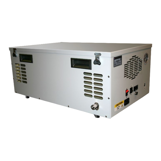
ACS3920
CO2 Free / Dry Air Compressor System
Thunder Scientific Corporation
®
623 Wyoming Blvd. SE Albuquerque, New Mexico 87123-3198
Ordering: (800) 872.7728 Tel: (505) 265.8701 FAX: (505) 266.6203
www.thunderscientific.com
Copyright © 2021 by Thunder Scientific Corporation, All Rights Reserved
1
Thunder Scientific Corporation ACS3920 Air Compressor System
Document Number: ACS3920.doc - Edition 04 - Nov 2021
Advertisement
Table of Contents

Related Manuals for Thunder Scientific ACS3920


Summary of Contents for Thunder Scientific ACS3920
- Page 1 623 Wyoming Blvd. SE Albuquerque, New Mexico 87123-3198 Ordering: (800) 872.7728 Tel: (505) 265.8701 FAX: (505) 266.6203 www.thunderscientific.com Copyright © 2021 by Thunder Scientific Corporation, All Rights Reserved Thunder Scientific Corporation ACS3920 Air Compressor System Document Number: ACS3920.doc - Edition 04 - Nov 2021...
- Page 2 ACS3920 Operation and Maintenance Manual Document Edition – 004 November 2021 THUNDER SCIENTIFIC® is the registered trademark of Thunder Scientific Corporation. All the information provided in this document is correct and true at the time of publication. Thunder Scientific Corporation ACS3920 Air Compressor System...
-
Page 3: Table Of Contents
SCHEMATICS ......................14 Pneumatic Schematic..................14 Electrical Schematic 110 VAC ................15 Electrical Schematic 220 VAC ................16 TROUBLESHOOTING GUIDE ................... 17 PARTS LIST ........................ 17 Thunder Scientific Corporation ACS3920 Air Compressor System Document Number: ACS3920.doc - Edition 04 - Nov 2021... -
Page 4: Introduction
ACS3920. You will only be able to generate down to around a -70 °C frost point when using the ACS3920. It is also important to adjust the internal Model 3920 or Model 3900 regulator to 80 to 90 psiG to assure proper pressure control. -
Page 5: Safety Guidelines
If possible, save shipping container for future use. Location Locate the ACS3920 on the floor with the outlet within five feet of the generator’s gas inlet and at least 12 inches away from the wall or other obstructions that would restrict the flow of air to or from the ventilation openings. -
Page 6: Air Supply Tubing
Air Supply Tubing Connect the 1/8” OD air supply tubing between the ACS3920 outlet and the generator’s gas inlet. The VCR type fitting connections require that face seal gaskets must be used. Power The ACS3920 is equipped with a power receptacle (RCP1) and cord having a grounding wire with an appropriate grounding plug. -
Page 7: Air Compressor
The Outlet Pressure Regulator (REG3) controls the pressure available from the CO2 Adsorber/Dryer to the ACS3920 outlet and is indicated on pressure gauge G3 (viewable inside unit with top cover removed). This pressure is factory set to the maximum outlet pressure of 100 psiG as indicated on the pressure gauge (G3) and should not require adjustment. -
Page 8: Dimensional Drawings
Dimensional Drawing Refer to drawing: ACS39001-115 Thunder Scientific Corporation ACS3920 Air Compressor System Document Number: ACS3920.doc - Edition 04 - Nov 2021... -
Page 9: Component Locations
23. Pressure Regulator (REG3) 11. Pressure Gauge (G2) 24. Remote/Manual Switch (S1) 12. Pressure Gauge (G3) 25. Solenoid Valve (SOL1) 13. Heat Limit Switch (HLS) Thunder Scientific Corporation ACS3920 Air Compressor System Document Number: ACS3920.doc - Edition 04 - Nov 2021... - Page 10 Thunder Scientific Corporation ACS3920 Air Compressor System Document Number: ACS3920.doc - Edition 04 - Nov 2021...
-
Page 11: General Operation
Be sure the "Air Supply Tubing" installation of paragraph 4.3 has been completed before proceeding. Insure the ACS3920 circuit breaker power switch is in the OFF position. Insert the power cord into the ACS3920 power receptacle and secure receptacle clamp. Plug the power cord into an AC mains outlet of the appropriate voltage, frequency, and current capacity as indicated by the equipment label. -
Page 12: Filter Inspection And Replacement
Re-install filter assembly using a backup wrench on inlet elbow turning clockwise. k. Reconnect compressor outlet hose to filter inlet. Snap membrane dryer back into place. Particulate Filter (LF1) Thunder Scientific Corporation ACS3920 Air Compressor System Document Number: ACS3920.doc - Edition 04 - Nov 2021... -
Page 13: Storage Procedures
Apply power and run the compressor "open" for at least five minutes. e. Disconnect power, cap compressor outlet. The ACS3920 is now ready for long term storage. Service Kit Refer to Gast Manufacturing 71R Series Rocking Piston Oil-Less Pump Operating and Maintenance Manual for parts and procedures. -
Page 14: Schematics
SCHEMATICS Pneumatic Schematic Refer to drawing: 21M3920325-B Figure 1-1 Thunder Scientific Corporation ACS3920 Air Compressor System Document Number: ACS3920.doc - Edition 04 - Nov 2021... -
Page 15: Electrical Schematic 110 Vac
Electrical Schematic 110 VAC 110 VAC Refer to drawing: ACS39001-115-F Figure 1-2 Thunder Scientific Corporation ACS3920 Air Compressor System Document Number: ACS3920.doc - Edition 04 - Nov 2021... -
Page 16: Electrical Schematic 220 Vac
Electrical Schematic 220 VAC 220 VAC Refer to drawing: ACS39001-220-F Figure 1-3 Thunder Scientific Corporation ACS3920 Air Compressor System Document Number: ACS3920.doc - Edition 04 - Nov 2021... -
Page 17: Troubleshooting Guide
Valve, Solenoid U147121-110 SSR-AC0 Relay, Solid State UPD Dual Output UPD2415DF Switch, Heat Limit CAP-MR-140-SS Desiccant Towers, MCA6 Adsorber/Dryer 51386 Service Kit, Gast Compressor K634 Thunder Scientific Corporation ACS3920 Air Compressor System Document Number: ACS3920.doc - Edition 04 - Nov 2021... - Page 18 This Page Intentionally Left Blank Thunder Scientific Corporation ACS3920 Air Compressor System Document Number: ACS3920.doc - Edition 04 - Nov 2021...
Need help?
Do you have a question about the ACS3920 and is the answer not in the manual?
Questions and answers