Advertisement
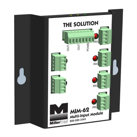
The Solution
READ AND UNDERSTAND ALL INSTRUCTIONS BEFORE BEGINNING INSTALLATION
MIM-62 connects up to 6 monitored entrapment protection devices to 1 or 2 operator inputs. It is recommended that you
read the following instructions completely before begining installation. Please also reference your operator's manual to
determine power and input requirements.
•
MIM-62 will accept up to 6 separate monitored devices and connect them to either of two outputs. Non-monitored
•
Input Channels 1 and 2 must be used, and are always assigned to Output A. The other input channels
devices will not work with MIM-62.
may be assigned to either Output A or Output B using the Input Assignment Switch on the rear panel.
Use of all 6 inputs is not required.
•
Each of the Output circuits of MIM-62 may be set to "Relay" (10K termination or normally closed), or "Pulsed" (like
photo-eye output signals), by the Output Type selection switch on the rear panel, and Terminal Connection choice
on P1.
•
MIM-62 may be powered from any 12 or 24 VAC/DC source that can supply at least 130 mA.
•
MIM-62 can provide an unregulated DC voltage to each monitored device; this voltage is dependent upon the
input supplied to MIM-62. The operator must supply enough current to power the devices and MIM-62 together.
1-
Pre-Installation Worksheet
Use the chart below to determine which input devices you will associate with each output when they are
connected to the operator.
Input #
Device Type
1
2
3
4
5
6
*All normally closed inputs must use power from MIM-62. 75 mA maximum per channel.
Multi-Input Module
IMPORTANT:
Location
www.GateOpenerSafety.com
Model: MIM-62
Output A/B
A
A
MIM-62
TOTAL CURRENT:
Current Draw
From MIM-62*
mA
mA
mA
mA
mA
mA
130
mA
mA
Advertisement
Table of Contents

Summary of Contents for Miller Edge MIM-62
- Page 1 READ AND UNDERSTAND ALL INSTRUCTIONS BEFORE BEGINNING INSTALLATION MIM-62 connects up to 6 monitored entrapment protection devices to 1 or 2 operator inputs. It is recommended that you read the following instructions completely before begining installation. Please also reference your operator’s manual to determine power and input requirements.
- Page 2 Prepare a mounting location for MIM-62 inside the operator. Use the two mounting slots on the top cover of MIM-62. Note: Do not mount MIM-62 yet. The switches and the Learn button on the rear panel of MIM-62 must be accessed during installation.
- Page 3 All 3-Wire All 4-Wire 2-Wire Pulsed Devices Devices Sensing Edge Photo-Eye 2-5. Wire each of your monitored devices to the removable 4-pin connector as shown in Figure 2. If the device is polarity sensitive, identify the correct common/ground wires. You do not need to use all 6 inputs.
- Page 4 62 should display a brief light test followed by blinking of the Output A and Output B indicators. The Learn Mode LED on the rear panel will also be lit. This indicates that MIM-62 is in Learn Mode, and will display the present condition of each input channel’s sensor:...
- Page 5 Power: 12-24 VAC/DC nominal (8-30V max); typically 130 mA device power may be supplied from the operator or alternatively from an external supply Cable Connections: 18-22 AWG Note: when using a normally closed operator input, MIM-62 must connect to operator accessory power Dimensions: 4”W x 4.74”H x 1”D Indicator Lights:...
Need help?
Do you have a question about the MIM-62 and is the answer not in the manual?
Questions and answers