Table of Contents
Advertisement
Quick Links
1.Preface
T h a n k y o u f o r p u r c h a s i n g t h e S h o c k R e l a y T S B S C s e r i e s .
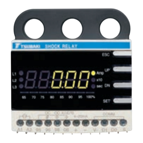
T h e S h o c k R e l a y i s a c u r r e n t m o n i t o r i n g d e v i c e t h a t q u i c k l y d e t e c t s m o t o r
o v e r l o a d , t h u s p r o t e c t i n g y o u r e q u i p m e n t f r o m c o s t l y d a m a g e .
T h i s i n s t r u c t i o n m a n u a l d e s c r i b e s e v e r y t h i n g f r o m i n s t a l l a t i o n t o a d j u s t m e n t .
B e s u r e t o r e a d t h i s m a n u a l c a r e f u l l y b e f o r e u s i n g y o u r S h o c k R e l a y .
W h e n d e l i v e r i n g a d e v i c e c o n t a i n i n g t h e S h o c k R e l a y , b e s u r e t h a t t h i s
i n s t r u c t i o n m a n u a l i s i n c l u d e d .
1. Make sure you read this instruction manual thoroughly before
installing, wiring, operation and inspecting this SHOCK RELAY.
2. Please make sure that this instruction manual accompanies the
SHOCK RELAY to the end user.
3. Product specifications are subject to change for improvement
without notice.
4. Disconnect power. Always lock out power switch before
installing, removing, or servicing unit. Comply with Occupational
Safety and Health Standards 1910. 147 "The Control of Hazardous
Energy (Lock Out/Tag Out)."
5. Install in proper enclosure in accordance with NEMA 250-1991
"Enclosures for Electrical Equipment (1000Volts Maximum)" and
NFPA496 1993 edition "Purged and Pressurized Enclosures for
Electrical Equipment, 1993 Edition." When revisions of these
standards are published, the updated edition shall apply.
6. Make sure you read this instruction manual thoroughly before
installing, wiring, operation and inspecting this SHOCK RELAY.
7. Please make sure that this instruction manual accompanies the
SHOCK RELAY to the end user.
8. Product specifications are subject to change for improvement
without notice.
1
Advertisement
Table of Contents

Subscribe to Our Youtube Channel
Related Manuals for Tsubaki SHOCK RELAY TSBSC Series

Summary of Contents for Tsubaki SHOCK RELAY TSBSC Series
- Page 1 1.Preface T h a n k y o u f o r p u r c h a s i n g t h e S h o c k R e l a y T S B S C s e r i e s . T h e S h o c k R e l a y i s a c u r r e n t m o n i t o r i n g d e v i c e t h a t q u i c k l y d e t e c t s m o t o r o v e r l o a d , t h u s p r o t e c t i n g y o u r e q u i p m e n t f r o m c o s t l y d a m a g e .
- Page 2 If danger is expected from your application, take the necessary steps to ensure that it operates safely. If your Tsubaki product does not operate normally, take care to ensure that dangerous operating conditions do not occur. Wear suitable clothing and protective equipment (safety glasses, gloves, safety shoes, etc.)
- Page 3 Outline All-in-one type TSBSCB06, TSBSCB34, TSBSCB60 Panel type TSBSCS06, TSBSCS34, TSBSCS60 Panel Unit TSBSCD Dimension for installing Cable SBSCC05, TSBSCC10, TSBSCC15, External CT TSB3CTC100, TSB3CTC200, TSBSCC20, TSBSCC30 TSB3CTC300...
-
Page 4: Specifications
Specifications... -
Page 5: Installation Method
. Installation method 6.1 Installation environment Make sure to install Shock Relay at the environmental condition shown in the attached table. 6.2 Main unit (1) Installation with screw Put the plate for installation at the both side of Shock Relay, and install Main unit to the panel. (2) Installation with DIN Rail While pulling the hook of Shock Relay to the arrow direction, install Shock Relay to 35mm DIN rail. -
Page 6: Explanation Of Each Part
8. Explanation of each part 8.1 Operation portion... -
Page 7: Setting Procedure
9.Setting procedure... - Page 8 10. Number of wires that pass through the CT (Current Transformer) hole...
- Page 9 Parameter...
- Page 10 Max. Current Current balancerat X100 Max. Current...
- Page 13 close close...
-
Page 14: Wiring Diagram
Wiring diagram Single- - phase motor Circuit breaker Overcurrent relay Fuse Magnetic contactor Transformer . Communication function... - Page 15 Phenomenon Check item Check result Treatment Wiring of the power It isn't being wired It is wired properly. source (A1-A2) LED indication isn't Check power It is different from turned on A proper power source voltage by proper supply voltage supply is input.
-
Page 16: Warranty
Buyer’s expense. 5. Disclaimer 1) In our constant efforts to improve, Tsubaki may make changes to this document or the product described herein without notice.Considerable effort has been made to ensure that the contents of this document are free from technical inaccuracies and errors. However, any such inaccuracies or errors reported will be gladly examined and amended as necess ary.
Need help?
Do you have a question about the SHOCK RELAY TSBSC Series and is the answer not in the manual?
Questions and answers