
Related Manuals for mundoclima CL04424


Summary of Contents for mundoclima CL04424
- Page 1 Cassette 4 Ways FCU DC Service manual MUCS-W7 CL04422 to CL04424 English www.mundoclima.com...
-
Page 2: Table Of Contents
Two-pipe Four-way Cassette DC Fan Coil Unit 1. External Appearance ............... 2 2. Features ................... 2 3. Product lineup ................. 3 4. Accessories ................4 5. Specifications ................5 6. Capacity Table ................. 7 7. Sound Levels ................. 22 8. Dimension ................22 9. -
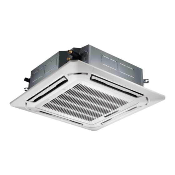
Page 3: External Appearance
1. External Appearance 2. Features 4-way air supply panel is standard, 360 air supply panel is optional. 360° Panel Unique design of the centrifugal fan ensures extra-quiet operation and high efficiency. Wireless remote control with LED display, wired control is optional. Safety grill for safety maintenance. -
Page 4: Product Lineup
Excellent efficiency DC FCU adopt the brushless DC motor, the DC motor efficiency is up to 90%. In contrast with the original FCU, DC FCU power consumption can be reduced by more than 30%. DC brushless motor The motor uses fully enclosed structure design, it is an energy-saving of high operating efficiency and durable motor. The motor bearing can operate 80,000 hours continuously and easy for maintenance. -
Page 5: Accessories
4. Accessories 4.1 Standard accessories Accessory name Qty. Shape Usage Owner’s & installation manual Installation paper board Bolt M6 Tubing& Fittings Soundproof / insulation sheath Out-let pipe Out-let pipe sheath Drainpipe Fittings Out-let pipe clasp Tightening band Remote controller R05/BGE-20 Frame Remote controller&... -
Page 6: Specifications
5. Specifications (none) Model (none) MUCS-20-W7 Power supply V/Ph/Hz 220-240/1/50 1175/987/768 1229/1020/810 1451/1146/1012 Air flow (H/M/L) 691/580/451 722/600/476 853/674/595 Capacity (H/M/L) 5.93/5.3/4.4 6.12/5.45/4.6 7.52/6.46/5.89 Water flow 1.05/0.92/0.77 1.10/0.96/0.81 1.37/1.18/1.07 rate(H/M/L) Cooling Water pressure 19.2/15.4/11 21.3/21.3/12.4 20.1/15.3/12.6 drop(H/M/L) Power input(H/M/L) 41/27/17 49/31/20 68/37/30 Capacity (H/M/L) - Page 7 (none) MUCS-24-W7 MUCS-36-W7 Model Power supply V/Ph/Hz 220-240/1/50 1530/1224/1101 1581/1371/1236 1871/1415/1198 Air flow (H/M/L) 900/720/647 930/806/727 1100/832/704 Capacity (H/M/L) 7.84/6.84/6.35 7.87/7.12/6.67 11.19/8.82/7.48 Water flow rate(H/M/L) 1.43/1.24/1.13 1.44/1.28/1.22 1.96/1.53/1.28 Cooling Water pressure 22/17/14.1 22.3/18.1/16.3 36.6/22.7/16.4 drop(H/M/L) Power input(H/M/L) 75/42/34 85/59/45 126/58/39 Capacity (H/M/L) 8.49/8/7.35 9.16/8.54/7.9...
-
Page 8: Capacity Table
6. Capacity Table Cooling Capacity Table (none) Indoor temperature (D.B.) Indoor EWT ΔT temp (W.B.) WF WPD TC WF WPD TC WF WPD TC WF WPD TC [m^3/ [m^3/ [m^3/ [m^3/ [kW] [kW] [kPa] [kW] [kW] [kPa] [kW] [kW] [kPa] [kW] [kW] [kPa] [kW] [kW] [m^3/h] [kPa] 4.95 3.85 1.42 25.62 4.92 4.44 1.41 25.39 5.04 5.04 1.44 26.45 5.57 5.57 1.59 31.41 6.1... - Page 9 (Continued) (none) Indoor temperature (D.B.) Indoor EWT ΔT temp (W.B.) WF WPD TC [kW] [kW] [m^3/ [kW] [kW] [m^3/ [kPa] [kW] [kW] [m^3/h] [kPa] [kPa] [kW] [kW] [m^3/h] [kPa] [kW] [kW] [m^3/h] [kPa] 2.27 2.27 0.65 6.48 2.82 2.82 0.81 9.39 3.37 3.37 0.97 12.71 3.92 3.92 1.12...
- Page 10 MUCS-20-W7 Indoor temperature (D.B.) Indoor EWT ΔT temp (W.B.) WF WPD TC WF WPD TC WF WPD TC WF WPD /h kPa /h kPa /h kPa /h kPa 5.06 3.95 1.45 26.66 5.04 4.56 1.44 26.45 5.18 5.18 1.48 27.75 5.72 5.72 1.64 32.86 6.27 6.27 38.52 6.59 3.84 1.89 42.01 6.56 4.45 1.88 41.67 6.52 5.05 1.87 41.27 6.32 5.57 1.81 39.21 6.35...
- Page 11 (Continued) MUCS-20-W7 Indoor temperature (D.B.) Indoor EWT ΔT temp (W.B.) WF WPD TC WF WPD TC WF WPD /h kPa /h kPa /h kPa kW m 2.33 2.33 0.67 6.77 0.83 9.81 3.46 3.46 0.99 13.29 4.02 4.02 1.15 17.18 4.58 4.58 1.32...
- Page 12 (none) Indoor temperature (D.B.) Indoor EWT ΔT temp (W.B.) WF WPD TC WF WPD TC WF WPD TC WF WPD TC /h kPa /h kPa /h kPa /h kPa 6.47 4.99 1.85 20.28 6.43 5.74 1.84 20.05 6.51 6.51 1.86 20.51 7.19 7.19 2.06 24.3 7.88 7.88 2.26 28.43 8.42 4.87 2.41 31.83 8.38 5.63 2.4 31.57 8.28 6.35 2.37 30.95 7.99 6.97 2.29 29.08 8.07 7.76 2.31...
- Page 13 (Continued) (none) Indoor temperature (D.B.) Indoor EWT ΔT temp (W.B.) WF WPD TC WF WPD TC WF WPD TC WF WPD TC /h kPa /h kPa /h kPa /h kPa 2.94 2.94 0.84 4.99 3.65 3.65 1.05 7.31 4.36 4.36 1.25 9.87 5.06 5.06 1.45 12.73 5.76 5.76 1.65 15.87 2.85 1.03 7.12 3.83 3.71 7.92 4.36 4.36 1.25 9.88 5.07 5.07 1.45 12.74 5.77 5.77 1.65...
- Page 14 (none) Indoo Indoor temperature (D.B.) ΔT temp (W.B. WF WPD TC WF WPD TC WF WPD TC /h kPa /h kPa /h kPa 6.72 1.92 21.62 6.68 5.98 1.91 21.39 6.78 6.78 1.94 21.97 7.49 7.49 2.14 26.06 8.21 8.21 2.35 30.5 8.74 5.07...
- Page 15 (Continued) (none) Indoor temperature (D.B.) Indoor EWT ΔT temp (W.B.) WF WPD TC WF WPD TC WF WPD TC WF WPD TC /h kPa /h kPa /h kPa /h kPa 3.06 3.06 0.88 5.38 1.09 7.83 4.54 4.54 1.3 10.58 5.28 5.28 1.51 13.65 1.72 17.03 3.74 2.97 1.07 7.59 3.98 3.87 1.14 8.45 4.54 4.54...
- Page 16 MUCS-24-W7 Indoor temperature (D.B.) Indoor EWT ΔT temp (W.B.) kW m kW m kW m 6.75 5.23 1.93 21.82 6.72 6.02 1.92 21.62 6.84 6.84 1.96 22.32 7.55 7.55 2.16 26.4 8.27 8.27 2.37 30.91 8.79 5.1 2.52 34.29 8.75 5.89 2.51 34.01 8.68 6.67 2.49 33.56...
- Page 17 (Continued) MUCS-24-W7 Indo Indoor temperature (D.B.) ΔT temp WF WPD TC WF WPD TC WF WPD TC WF WPD TC (W.B. /h kPa /h kPa /h kPa /h kPa 3.08 3.08 0.88 5.45 3.83 3.83 7.92 4.57 4.57 1.31 10.71 5.32 5.32 1.52 13.82 6.05 6.05 1.74 17.25 3.75 2.99 1.07 7.63...
- Page 18 MUCS-36-W7 Indoor temperature (D.B.) Indoor EWT ΔT temp (W.B.) WF WPD WF WPD TC WF WPD TC WF WPD TC kW m /h kPa /h kPa /h kPa /h kPa 9.34 7.14 2.67 19.83 9.19 8.14 2.63 19.29 9.3 9.25 2.66 19.7 10.23 10.23 2.93 23.17 11.19 11.19 3.2 27.05 12.14 3.48 31.08 12.05 8.04 3.45 30.71 11.7 8.95 3.35 29.16 11.54 9.94...
- Page 19 (Continued) MUCS-36-W7 Indoo Indoor temperature (D.B.) ΔT temp WF WPD TC WF WPD TC WF WPD TC WF WPD TC (W.B. /h kPa /h kPa /h kPa /h kPa 4.19 4.19 4.72 5.21 5.21 1.49 7.01 6.21 6.21 1.78 9.45 7.21 7.21 2.07 12.15 8.19 8.19 2.35 15.12 5.25 4.08 1.51 7.11 5.53 5.27 1.58 7.75 6.22 6.22 1.78 9.47 7.21 7.21 2.07 12.16 8.19 8.19 2.35 15.13...
- Page 20 Heating Capacity Table (none) Indoor temperature (D.B.) ΔT 5.93 1.03 11.91 5.35 0.93 9.98 4.78 0.83 0.73 6.59 5.76 0.83 8.29 5.18 0.75 6.91 0.66 5.64 4.02 0.58 4.49 0.58 4.57 4.82 0.52 3.76 4.24 0.46 3.03 3.66 2.36 5.03 0.44 2.79 4.44...
- Page 21 (none) Indoor temperature (D.B.) ΔT 7.83 1.36 9.55 7.06 1.22 1.09 6.58 5.54 0.96 5.28 6.66 6.83 0.99 5.55 6.07 0.88 4.54 5.31 0.77 3.61 7.13 0.77 3.68 6.36 0.69 3.03 0.61 2.44 4.83 0.52 6.65 0.58 2.25 5.87 0.51 1.81 0.44 1.29...
- Page 22 MUCS-24-W7 Indoor temperature (D.B.) ΔT [kW] [m^3/h] [kPa] [kW] [m^3/h] [kPa] [kW] [m^3/h] [kPa] [kW] [m^3/h] [kPa] 8.61 1.49 11.26 7.77 1.35 9.43 6.93 7.75 1.06 6.22 8.36 1.21 7.84 7.52 1.09 6.53 6.68 0.96 5.33 5.84 0.84 4.25 7.85 0.85 4.33 0.76...
-
Page 23: Sound Levels
7. Sound Levels MUCS-20-W7 MUCS-24-W7 MUCS-36-W7 H/M/L [dB(A)] 44/40/34 48/44/41 49/43/39... -
Page 24: Dimension
8. Dimension Model MUCS-20-W7 MUCS-24/36-W7... -
Page 25: Service Spaces
9. Service Spaces Model MUCS-20-W7 >260 MUCS-24/36-W7 >330... -
Page 26: Wiring Diagrams
10. Wiring Diagrams... - Page 27 Table A MODEL DIP SW1 CODE DESCRIPTION FAN MOTOR V1-2 WATER VALVE (none) ROOM TEMP. SENSOR PIPE TEMP. SENSOR PIPE TEMP. SENSOR XP1-7, XS1-7 CONNECTORS MUCS-20-W7 TERMINAL TERMINAL FUSE PROTECTOR SWITCH OVER HEAT (none) AUXILIARY HEATER WATER LEVEL SWITCH PUMP PUMP MOTOR (none) Notes:...
-
Page 28: Troubleshooting
11. Troubleshooting Troubles and causes of air conditioner If one of the following malfunctions occur, stop operation, shut off the power, and contact with your dealer. „ The operation lamp is flashing rapidly (five times per second), you disconnect the unit with the power and then connect the unit with the power again after two or three minutes but the lamps still flash. - Page 29 Troubles and causes of remote controller Before asking for serving or repairing, check the following points. Symptoms Causes Solution • Check whether the MODE When the automatic mode is indicated on the display is selected, the air conditioner will “AUTO” automatically change the fan speed.
-
Page 30: Installation
12. Installation 12.1 Before Installation Please check whether the accessories are of full scope. If there are some fittings free from use, please restore them carefully. 12.2 Installation space (Refer to fig.12.1, fig.12.2, fig.12.3 and table 12.1 for specification.) The indoor unit should be installed in a location that meets the following requirements: There is enough room for installation and maintenance. - Page 31 Adjust the position to ensure the gaps between the body and the four sides of ceiling are even. The body's lower part should sink into the ceiling for 10~12 mm (refer to fig.12.6). In general, L is half of the screw length of the installation hook. (refer to fig.12.6) Locate the air conditioner firmly by wrenching the nuts after having adjusted the body's position well.
- Page 32 fig. 12.5 fig. 12.6 fig. 12.7 fig. 12.8 fig. 12.9 fig. 12.10 12.5 Install the Panel Caution: Never put the panel face down on floor or against the wall, or on bulgy objects. Never crash or strike it. (1) Remove the air inlet grill. Slide two grid switches toward the middle at the same time, and then pull them up.
- Page 33 (2) Remove the installation covers at the four corners. Wrench off the bolts, loose the rope of the installation covers, and remove them. (Refer to fig. 12.10) (3) Install the panel Align the swing motor on the panel to the tubing joints of the body properly. Fix hooks of the panel at swing motor and its opposite sides to the hooks of corresponding water receiver.
- Page 34 backflow while shutdown would leads to overflow (refer to fig.12.12). „ Base on the actual requirement to bend piping, and use connective assembly of water outlet in terminal box for pipe layout. Caution: The joints in drain system must be sealed to avoid water leakage. „...
- Page 35 12.7 Wiring Caution: The air conditioner should use separate power supply with rated voltage. The external power supply to the air conditioner should have ground wiring, which is linked to the ground wiring of the indoor and outdoor unit. The wiring work should be done by qualified persons according to circuit drawing. An all-pole disconnection device which has at least 3mm separation distance in all pole and a residual current device (RCD) with the rating of above 10mA shall be incorporated in the fixed wiring according to the national rule.
- Page 36 12.7.2 Wiring figure...
- Page 37 Note: If the supply cord is damaged, it must be replaced by the manufacturer or its service agent or a similarly qualified person in order to avoid a hazard. 12.8 Test operation „ The test operation must be carried out after the entire installation has been completed. „...
- Page 38 ASK FOR MORE INFORMATION Phone: (+34) 93 446 27 81 eMail: info@mundoclima.com TECHNICAL ASSISTANCE Phone: (+34) 93 652 53 57 www.mundoclima.com...
Need help?
Do you have a question about the CL04424 and is the answer not in the manual?
Questions and answers