
Summary of Contents for Aegis ATC-HZ5510C-LCN
- Page 1 DATE 05,May, 2020 Messrs. Rev No. APPROVAL SHEET Global Shutter Zoom Camera Series Description ATC-HZ5510C-LCN Model Name Receipt stamp Issued Checked Approved P402-05(4)
- Page 2 Revision History Date Rev. No Contents 2019.05. Rev.1.0 Release Document...
-
Page 3: Table Of Contents
ABLE OF CONTENTS TABLE OF CONTENTS ---------------------------------------------------- FEATURES ---------------------------------------------------- PRECAUTION ---------------------------------------------------- SPECIFICATIONSS ---------------------------------------------------- DIMENSIONS ---------------------------------------------------- INTERFACE ---------------------------------------------------- OSD & MENU ---------------------------------------------------- FUNCTIONS ---------------------------------------------------- COMMAND LIST ----------------------------------------------------... -
Page 4: Features
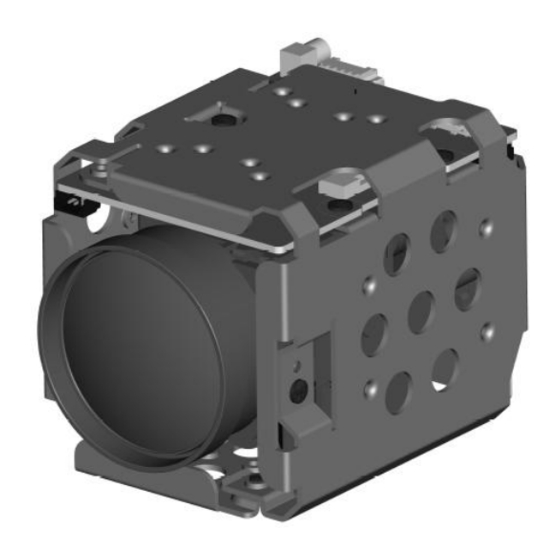
• Using progressive scan, images with a wide dynamic range can be obtained with the newly ATC-HZ5510C-LCN developed image signal processor (Wide Dynamic Range function, WDR). • The camera is equipped with a bright zoom lens with 10×... -
Page 5: Precaution
RECAUTION Operation is subject to the following conditions; • This device may not cause harmful interference. • Never face the camera towards the sun or any • This device must accept any interference bright or reflective light, which may cause received, including interference that may cause smear on the image and possible damage to the undesired operation. -
Page 6: Specificationss
PECIFICATIONS Format / Model ATC-HZ5510C-LCN ATC-HZ5510C-P Video System Image Sensor 1/2.9”1.58M Global shutter CMOS Image Sensor Effective Pixels 1456(H)x1088(V), Unit Cell Size(3.45µm X 3.45µm) Output Format LVDS/PARALLEL/CVBS : 1080p60/50/30/25, 720p60/50/30/25, 1080i60/50 Sensor Output : FULL/CROP Video Output : FULL/CROP Sensor Operating System... - Page 7 Format / Model ATC-HZ5510C-LCN ATC-HZ5510C-P DSP functions Digital Slow Shutter Max. 32 fields Image Freeze Off / On Image Reverse (E-FLIP) Off / Horizontal(mirror) / Vertical / H+V(180° flip) Privacy Masking Spherical Privacy - 8-zone - Interlock / Non-Interlock Mask - 14 mask color selectable, semi-transparency - Pan(0°~360°), Tilt(+90°~-90°)
- Page 8 INTERFACE SUMMARY ATC-HZ5510C-LCN ATC-HZ5510C-P Interface & Video ◎ PARALLEL Video CVBS Output ◎ LVDS MMCX 32pin Micro Coaxial ◎ (USL00-30L-A, 0.4mm) 36pinFFC ◎ (FH12-36S-0.55H, 0.55mm) 8pin External Sync (SM08B-SRSS-TB, 1.0mm) Interface 5pin CVBS&ADKey&12V (SM05B-SRSS-TB, 1.0mm) 5pin Trigger&Strobe (SM05B-SRSS-TB, 1.0mm) 3pin External D&N (SM03B-SRSS-TB, 1.0mm)
- Page 9 IMENSION ATC-HZ5510C-LCN DIMENSIONS...
- Page 10 DIMENSIONS ATC-HZ5510C-P...
-
Page 11: Interface
NTERFACE INTERFACE ATC-HZ5510C-LCN CN301 CN303/SM03B-SRSS-TB J303 … Name Description … EXT_DN External D&N Input +3.3V +3.3V Out (For Sensor) CN303 CN307/SM03B-SRSS-TB Name Description CN307 UART_RX UART_RX UART_TX UART_TX J303 (LVSDS)/USL00-30L-A CN302 Name Description TX_OUT3+ TX_OUT3- TX_CLKOUT+ LVDS_CLK TX_CLKOUT- LVDS_CLK TX_OUT2+... - Page 12 INTERFACE ATC-HZ5510C-P CN303/SM03B-SRSS-TB Name Description CN301 J304 EXT_DN External D&N Input … … +3.3V +3.3V Out (For Sensor) CN307/SM03B-SRSS-TB Name Description CN303 UART_RX UART_RX UART_TX UART_TX J304 (PAEALLEL)/ FH12-365-0.55H Name Description Y_OUT[0]- Y_OUT[1]- CN302 CN307 Y_OUT[2]-- Y_OUT[3]- Y_OUT[4]- Y_OUT[5]- Y_OUT[6]- SW101 Y_OUT[7]- C_OUT[0]...
- Page 13 LVDS interface (LVDS model only) CAMERA THC63LVD104C (Single only) THC63LVD1024 (Single/Double) (THINE Electronics Inc.) LVDS(single) (5pairs / 10pin) Y (8bits X 2) Y (8bits X 2) Cb/Cr Cb/Cr LVDS Parallel LVDS(double) (5pairs / 10pin) LVDS Parallel J303 (Micro Co- Axial) KEL Co.
- Page 14 LVDS Pixel Data Format (LVDS model only) Single Mode : THC63LVD827 (THINE Electronics Inc.) (THC63LVD827 IN) Pixel Clock Pixel Data (THC63LVD827 OUT) TCLK1 +/- TA1 +/- TB1 +/- TC1 +/- TD1 +/- * : ignore this value Output Format Pixel Clock [MHz] TCLK+ [MHz] 1080p60 148.5...
- Page 15 Double Mode : THC63LVD827 (THINE Electronics Inc.) (THC63LVD827 IN) Pixel Clock Pixel Data 1’st pixel 2’nd Pixel (Odd) (Even) (THC63LVD827 OUT) TCLK1 +/- TA1 +/- 1’st pixel TB1 +/- TC1 +/- TD1 +/- TA2 +/- 2’nd pixel TB2 +/- TC2 +/- TD2 +/- * : ignore this value Output Format...
- Page 16 LVDS Receive Circuit Example (LVDS model only) LVDS Single Output receiver circuit example / Receiver IC : THC63LVD104C...
- Page 17 LVDS Single Output receiver circuit example / Receiver IC Pin Assign : THC63LVD104C Pin No. Description Signal Pin No. Description Signal GND0 TEST VSYNC VCC2 HSYNC VCC0 GND3 GND1 VCC3 TXOUT0- TXOUT0+ TXOUT1- TXOUT1+ LVCC TXOUT2- VCC1 TXOUT2+ RCLK- TXCLKOUT- RCLK+ TXCLKOUT+ LGND...
- Page 18 LVDS Single Output receiver circuit example / Receiver IC : THC63LVD1024...
- Page 19 LVDS Double Output receiver circuit example / Receiver IC : THC63LVD1024...
- Page 20 LVDS Single/Double Output receiver circuit example / Receiver IC Pin Assign : THC63LVD1024 Pin No. Description Signal Pin No. Description Signal Pin No. Description Signal PGND HSYNC PVCC VSYNC RESERVED FSYNC PDWN CONT11 MODE0 CONT21 CONT12 MODE1 MODE1 CONT22 PVCC PGND LGND MODE2...
- Page 21 SD & MENU 1’ST ITEM 2’ND ITEM 3’RD ITEM or DATA 4’TH ITEM or DATA 5’TH ITEM or DATA FOCUS AF MODE AUTO/INTERVAL/ONE PUSH/MANUAL/PRESET DZOOM OFF/ON ZOOM START 1~10 ZOOM STOP 1~120 ZOOM SPEED FOCUS LIMIT 1CM/3CM/10CM/20CM.30CM/50CM/80CM/1M/1.5M/2M/3M/5M/10M/30M/INF AF INTERVAL 1~255 STANDARD/IR LIGHT/USER -20~+20 IR CORRECT 0~255...
- Page 22 INITIAL RETURN DAY&NIGHT MODE AUTO/DAY(COLOR)/NIGHT(BW)/EXT-H/EXT-L DELAY[SEC] 1~60 D->N LEVEL 1~255 N->D LEVEL 1~254 NIGHT COLOR OFF/ON COLOR BURST OFF/ON INITIAL RETUEN IMAGE SHARPNESS 0~15 CONTRAST 0~20 GAMMA 0.4/0.45/0.5/0.55/0.6/0.7/0.8/0.9/1.0 SHADING OFF/ON FREEZE OFF/ON EFFECT OFF/NEGATIVE/GRAY MODE/REDDISH-1~4/BLUISH-1~4/GREENISH-1~4 ROTATE MIRROR OFF/H-FLIP/V-FLIP/HV-FLIP CORRIDOR VIEW OFF/FULL/CROP RETURN MODE...
- Page 23 RED/CYAN/MAGENTA/YELLOW/MOSAIC POSITION-X 0~160 POSITION-Y 0~90 SIZE-X 1~80 SIZE-Y 1~45 MASK RESET PUSH INITIAL RETURN MOTION MODE OFF/ON AREA NO AREA ENABLE OFF/ON AREA SET POSITION-X 0~89 ( 79) POSITION-Y 0~69 (49) OUTPUT SCAN FULL, OUTPUT SCAN CROP SIZE-X 0~90 ( 80) SIZE-Y 0~70 ( 50)
- Page 24 WIDTH OFFSET -127~128 STROBE REPEAT OFF/ON/ENDLESS REPEAT COUNT 2~255 RESET RETURN RETURN MENU SET LANGUAGE DEFAULT/TOP-LEFT,RIGHT/BOT-LEFT,RIGHT MENU POSITION MENU COLOR TEXT COLOR WHITE/YELLOW/GR AY/BLUE/BLACK/BLA TEXT(H) COLOR CK OP/WHITE OP/ B/G COLOR NO COLOR B/G(H) COLOR RETURN OSD TYPE NORMAL/CVBS RETURN LVDS SET LVDS MODE SINGLE/DUAL...
-
Page 25: Functions
UNCTIONS Auto Focus Near Limit (!!!) Memory Control Function Priority You can set the minimum focus distance from 1cm(or 10cm) to infinite. It is available only at high magnification zoom Function Priority position. D-ZOOM Digital Zoom Function This is called by FOCUS LIMIT or NEAR LIMIT or M.O.D Wide Dynamic Range (Minimum object distance). - Page 26 Back-Light Compensation(BLC) Automatic Exposure Mode BLC allows the camera to adjust the exposure of the entire ● Full Auto mode image to properly expose the subject in the foreground. Iris, Gain, Shutter speed can be set automatically. ● Shutter Priority mode Variable shutter speed : 1/1(X32)~1/10000 Auto Iris &...
- Page 27 White Balance ● MANUAL Adjust color manually. Setting blue gain and red There is a difference between the colors that people gain(0~255). perceive and the colors that the camera recognizes. White Balance is used to overcome or reduce the difference. ●...
- Page 28 Day & Night Setting ●EXT-L/H Mode DAY / NIGHT is determined according to the external Day&Night Mode input signal. In EXT-H mode, when the input signal level is greater CAM_ICR 8x 01 04 01 0p FF p=2(ICR ON) than DAY TO NIGHT LEVEL, it switches to NIGHT. p=3(ICR OFF) In EXT-L mode, if the input signal level is lower than DAY CAM_AutoICR...
- Page 29 Defog Digital Image Stabilizer (DIS) • This function reduces image blurring caused by • Sharpens cloudy images such as fog. vibration • CVBS is turned off when DIS mode is ON. CAM_Defog 8x 01 04 37 0p 00 p=2(ON) / 3(OFF) / 4(AUTO) KT_DefogOnLevel 8x 01 70 3C 0p 00...
- Page 30 Corridor View Image Mirror In many surveillance situations you want to monitor This function rotates the image. an area that is more vertical than horizontal in shape. This includes staircases, hallways, aisles, roads, runways, tunnels, and many other applications. In these situations, the traditional landscape format is not the optimal solution since it creates video streams where a large part of the field of view –...
- Page 31 Custom Preset Freeze As with the memory preset function, the camera This function captures an image in the field memory of shooting conditions can be saved and recalled. The the camera so that this image can be output settings are recalled when the power is turned on. continuously.
- Page 32 Title / Function Display Motion Detect Function The user can output desired characters on the screen Motion Detect functions instructs the camera to detect and can also choose the output font size. movement within monitoring area and then send an alarm See.“...
- Page 33 Privacy Zone Masking • Mask can be set on up to 8 places according to Pan/ Tilt positions. Privacy Zone masking protects private objects and • Interlocking control with zooming. areas such as house windows, entrances, and exits • Interlocking control with Pan/Tilt. which are within the camera’s range of vision but not •...
- Page 34 Pan/Tilt Angle Eclipse When designing the housing, refer to the dimensional allowance as shown in the figure below. You can use the tilt angle at which you can set the mask between -90 to + 90 degrees. But the recommended tilt angle is between –70 to +70 degrees.
- Page 35 Video Output Mode Global shutter Global shutter make images that not distorted without It is to set the angle of view range of the output video. wobble or skewing. This shutter uses visualize that object moving high speed. Sensor Scan Output Video Scan Output image FULL...
- Page 36 Trigger Control Trigger Mode Control Free run Mode The camera operates without a trigger signal and performs the video output operation continuously after the exposure is finished. The horizontal and vertical timing signals are generated within the Asynchronous Reset Mode (=Fast Trigger mode) camera.
-
Page 37: Command List
OMMAND LIST Overview of RS232 Communication Command & Inquiry Command Communication speed : Sends operational commands to the camera 2400/4800/9600/19200,38400/57600/115200bps Inquiry Data bits : 8 Start bit : 1 Used for inquiring about the current state of the ... - Page 38 Error message Inquiries Error Packet Description X0 6Y 01 FF Message length error (>14 bytes) X0 6Y 02 FF Syntax Error ACK message X0 6Y 03 FF Command Buffer Full X0 6Y 04 FF Command cancelled X0 6Y 05 FF No socket Returned by the camera when it receives a...
- Page 39 CAMERA COMMAND LIST Command Set Command Command Packet Comments AddressSet Broadcast 88 30 01 FF Address setting IF_Clear Broadcast 88 01 00 01 FF I/F Clear CommandCancel 8x 2p FF p: Socket No. (=1 or 2) CAM_Power 8x 01 04 00 02 FF Power ON/OFF Off (Standby) 8x 01 04 00 03 FF...
- Page 40 Direct 8x 01 04 43 00 00 0p 0q FF pq: R Gain, 0x00~0xff CAM_BGain Reset 8x 01 04 04 00 FF Manual Control of B Gain 8x 01 04 04 02 FF Down 8x 01 04 04 03 FF Direct 8x 01 04 44 00 00 0p 0q FF pq: B Gain, 0x00~0xff...
- Page 41 CAM_AutoICR 8x 01 04 51 02 FF Auto dark-field mode On/Off 8x 01 04 51 03 FF Threshold 8x 01 04 21 00 00 0p 0q FF pq: ICR ON → OFF Threshold Level (Night->Day) Threshold 8x 01 04 41 00 00 0p 0q FF pq: ICR OFF →...
- Page 42 pp pp pp pp: Mask Settings (0: OFF, 1: ON) SetMaskColor 8x 01 04 78 pp pp pp pp pp pp pp: Mask Color Settings pp qq rr FF qq: Color Setting when 0 is selected rr: Color Setting when 1 is selected SetPanTiltAngle 8x 01 04 79 0p 0p 0p...
- Page 43 8x 01 04 59 03 FF Position 8x 01 04 29 0p 0q 0r 0s FF pq:X(0~F), rs:Y(0~F) CAM_Memory Reset 8x 01 04 3F 00 0p FF p:Memory Number(0~F) (See. Custom/Memory Preset Setting Items) 8x 01 04 3F 01 0p FF Recall 8x 01 04 3F 02 0p FF CAM_Custom...
- Page 44 KT_Dnr Mode 8x 01 70 36 0p FF p:0(off) 1(2D) 2(3D) 3(2D+3D) Level 8x 01 70 39 0p 0q FF p:DNR level(0:auto,1:low,2:mid,3:high) q:DNR aperture(0~4) KT_WbSpeed 8x 01 71 50 0p FF p : Speed (0~7) KT_WbBluseoffset 8x 01 71 51 pp FF pp : Blue offset Value (0x00~0x64 ) KT_WbRedoffset 8x 01 71 52 pp FF...
- Page 45 Inquiry Command List Inquiry Command Command Packet Inquiry Packet Comments CAM_PowerInq 8x 09 04 00 FF y0 50 02 FF y0 50 03 FF Off (Standby) CAM_ZoomPosInq 8x 09 04 47 FF y0 50 0p 0q 0r 0s FF pqrs: Zoom Position CAM_DZoomModeInq 8x 09 04 06 FF y0 50 02 FF...
- Page 46 CAM_PictureEffectModeInq 8x 09 04 63 FF y0 50 00 FF y0 50 02 FF Neg.Art y0 50 04 FF B&W y0 50 1p FF p=1~B : RED1~4/BLUE1~4/GREEN1~4 CAM_PictureFlipModeInq 8x 09 04 66 FF y0 50 02 FF y0 50 03 FF CAM_ICRModeInq 8x 09 04 01 FF y0 50 02 FF...
- Page 47 CAM_MemoryInq 8x 09 04 3F FF y0 50 pp FF pp : memory number recalled last CAM_MinShutterInq 8x 09 04 12 FF y0 50 0p FF p : 2(on)/3(off) 8x 09 04 13 FF y0 50 00 00 0p 0q FF pq: min.
- Page 48 0(Off) / 1(H-flip) / 2(V-flip) /3(HV-flip) KT_PwrOnLensInitSkipInq 8x 09 70 49 FF y0 50 0p FF p : Focus reverse mode (2:on, 3:off) KT_DwdrModeInq 8x 09 70 4B FF y0 50 0p FF p : 0(off), 1(on), 2(auto) 8x 09 70 4C FF y0 50 0p FF p : Dwdr on level(0x00~0x0f) 8x 09 70 4D FF...
- Page 49 Lens Control System Inquiry Commands ....Command Packet 8x 09 7E 7E 00 FF Byte Comments Byte Comments Byte Comment Destination Address Focus Near Limit (H) Source Address 0 Completion Message (50h) DZoomMode 0: Combine 1: Separate 0: Normal 1: Interval 2: Zoom Trigger Focus Near Limit (L) AF Sensitivity 0:...
- Page 50 Camera Control System Inquiry Commands .... Command Packet 8x 09 7E 7E 01 FF Byte Comments Byte Comments Byte Comments Destination Address Source Address Gain Position Mode 0 Completion Message (50h) Bright Position Aperture Gain Exposure Mode R Gain (H) Exposure Comp.
- Page 51 Other Inquiry Commands ....Command Packet 8x 09 7E 7E 02 FF Byte Comments Byte Comments Byte Comments Destination Address Memory 1: Provided 0: Not provided Source Address ICR 1: Provided 0: Not provided Stabilizer 0 Completion Message (50h) 1:provided, 0: not provided 1: 1/50, 1/25 0: 1/60, 1/30 Day&Night Mode 0:auto...
- Page 52 Enlargement Function1 Query Command....Command Packet 8x 09 7E 7E 03 FF Byte Comments Byte Comments Byte Comments Destination Address Color Gain (0h (60%) to Eh (200%)) Advanced Privacy Source Address AF Interval Time (H) (1: Provided, 0: Not provided) Alarm (1: Provided, 0: Not provided) 0 Completion Message...
- Page 53 Enlargement Function2 Query Command....Command Packet 8x 09 7E 7E 04 FF Byte Comm Byte Comments Byte Comments ents Destination Address Source Address 0 Completion Message (50h) Defog Mode(1:on,0:off) WideD mode (0: OFF, 1: ON) 1 Terminator (FFh) WideD blown-out highlight correction level 0: L 1: M 2: H...
- Page 54 Enlargement Function3 Query Command....Command Packet 8x 09 7E 7E 05 FF Byte Comments Byte Comment Byte Comments Destination Address Reserved Reserved Source Address 0 Completion Message (50h) Reserved Reserved Reserved Reserved Reserved Reserved Reserved 1 Terminator (FFh) Reserved Reserved Reserved...
- Page 55 Command Setting Values GAIN LIMIT & GAIN POSITION AE BRIGHT MODE LEVEL SHUTTER SPEED Index Gain Index 60/30 mode 50/25 mode Index Iris Gain 45dB 1/10000 1/10000 28 dB F1.6 42dB 1/6000 1/6000 26 dB F1.6 1/4000 1/3500 39dB 24 dB F1.6 36dB 1/3000...
- Page 56 Lens Control Digital Zoom Position Zoom Position 0000 4000 7AC0 Digital Zoom Combine Separate Wide end Optical Digital Ratio Mode Mode Tele end Tele end 4000 Focus Position 1000 F000 6000 Far end Near end 6A80 Focus Near Limit 1000, // inf The Lower 1 byte 7000...
- Page 57 WB Data(Rgain,Bgain) Title Setting COLOR Gain AE Mode Line number 00 to 14h AE Response H-position 00 to 28h AE Slow Shutter Blink 00: Dose not blink Shutter Position 01: Blinks Iris Position Color White Gain Position Yellow Gain Limit Violet Bright Position Exposure Compensation Mode...
- Page 58 RS232 None parity Register Setting Parity Bit Odd parity Even parity CAM_RegisterValue 8x 01 04 24 mm: Register No. (=00-7F) mm 0p 0p FF pp: Register Value (=00-7F) Sensor Scan Full Mode Crop Register Value Output Scan Full command contents (mm) (pp) Mode...
- Page 59 Response to Tilt position input on the host zzzz : position KT_Reset FF 01 70 00 00 00 CS Set value reset KT_ResetEep FF 01 7E EE 00 00 CS Reset all system EEPROM, Reset to FACTORY DEFAULT status www.aegis-elec.com Phone: 760-729-2026...
Need help?
Do you have a question about the ATC-HZ5510C-LCN and is the answer not in the manual?
Questions and answers