Table of Contents
Advertisement
Quick Links
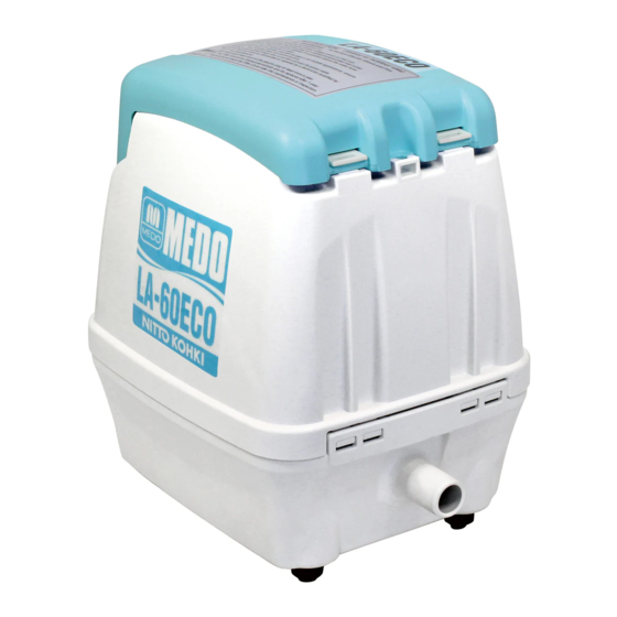
MEDO LA-ECO BLOWER MAINTENANCE MANUAL
This instruction manual should be read and understood
LA-60ECO
thoroughly before any maintenance work is executed.
Safety Instructions
Explanation of Diagrammatic Expressions
The term "Attention" as used in this manual is to alert you to dangers such as the following;
The degree of Danger Indicated by "Attention" clauses.
Clause
Such clauses indicate the possibility that continuing to work
while ignoring the "Attention" clause, or working with
ATTENTION
negligence, may cause personal injury or property damage.
The Meanings of the Symbols
Symbols
This symbol advises you of an item which should BE NOTED (including
Danger or Warning). Accompanying notes may include a picture or
explanatory text inside the triangle or next to the symbol mark
This symbol advises you of an action which must NOT BE TAKEN (IS
PROHIBITED) in order to avoid danger. The general actions which must
not be taken will be shown by a picture or explanatory text inside or next to
the symbol mark.
This symbol advises you of an action which must BE TAKEN (IS MANDA-
TORY) in order to avoid danger. The action which must be taken will be
shown by a picture or explanatory text inside the circle or next to the
symbol mark.
Safety and Operating Instructions
The following safety precautions should always be followed to reduce the risk of breakdown
and/or accidents.
ATTENTION
• • • To Prevent Electric Shock And Fire
1 Don't install the blower where it may be flooded with water and buried in snow.
2 Electric work must be done by a qualified electrician.
3 The power supply should be the rated voltage shown on the label on the blower and
be fitted with earth leakage and over current breakers.
4 The power outlet used should be waterproof and include an earth connected to the
ground.
5 If the power supply cord is damaged, it must be replaced by the manufacturer or its
service agent or similarly qualified person in order to avoid a hazard.
6 Don't place any objects on the power supply cord.
7 Be sure to unplug the blower before starting maintenance.
8 Be sure to replace the Upper Case and Filter Cover after maintenance.
9 Check for dust on the electric plug and clean it at least once a year.
Ignoring any of the above 1 - 9 may cause an electric shock or a fire.
0 Don't touch the metal part of the blower until it has cooled down as the blower runs
very hot.
Ignoring the above 0 may cause a burn.
Contents of Repair Parts Kit
Models
Parts No.
Parts Name
LB08038
Piston Set
LA-60ECO
LQ06685
Gasket A
LQ06856
Filter Element
Exploded View (LA-60ECO)
J Bind Screw 5x14
Lock flip of Filter Cover
Screwdriver blade slot
1 Bind Screw 5x25
2 Filter Cover
View A
F Middle Case
3 Filter Element
A
Never loosen Hex Bolts 5x30 (2 pcs.)
Gasket Air Cleaner
4 Upper Case
5 Gasket C
0 Piston Set
9 Cylinder
Side holes
8 Gasket A
Hooks
7 Cylinder Cover
6 Hex Bolts 5x16
All manuals and user guides at all-guides.com
Q'ty
1
1
1
C Silicon Hose
D Lead Wire
B Hex Bolts 5x25
E Connector A
Wiring guide No.1
Wiring guide No.2
Connector holder
Wiring guide No3
Screwdriver blade slot
U-shaped groove
A Blower Body
G Connector B
H Gasket B
I Bottom Case
Corresponding
latches
Lead Wire Bushing (black)
Air Outlet
Screwdriver blade slot
1. Cautions
(1) MEDO blowers are OILLESS. Never lubricate them.
(2) The A Blower Body has already been precisely adjusted. Never disassemble.
(Never loosen Hex Bolts 5x30 (2 pcs.) on the rear of A Blower Body.)
2. Replacement of Filter Element
(1) Be sure to unplug the blower before starting any work.
(2) If present, unscrew the J Bind Screw 5x14, and push the catch to open the 2 Filter Cover.
(3) Remove the 3 Filter Element from 4 Upper Case and replace with a new one.
At the same time, clean the air inlet of 2 Filter Cover and 4 Upper Case.
(4) Verify that Gasket Air Cleaner is correctly fitted to 4 Upper Case.
(5) Return 3 Filter Element to 4 Upper Case.
(6) Follow Instruction Label affixed to 2 Filter Cover and lock 2 Filter Cover with 4 Upper
Case by pushing within the dotted line area until Filter Cover lock audibly clicks into place.
(7) Tighten J Bind Screw 5x14.
(8) Filter Element Replacement Period.
It is recommended that the Filter Element(s) be cleaned or replaced with a new one(s)
depending on the extent of its deterioration as determined by the atmospheric conditions
around the installation point. Filter Element(s) should be checked every three months.
Replace Filter Element only with a genuine NITTO KOHKI part. Otherwise there is a risk
of damage or malfunction.
3. Replacement of Piston Set
(1) Be sure to unplug the blower before starting any work.
(2) Unscrew the 1 Bind Screw 5x25 of 4 Upper Case with cross slot screwdriver and remove
4 Upper Case.
(3) Disconnect C Silicon Hose from the wiring guide No.2.
(4) While pressing the fastening clip of E Connector A, pull it up to remove it from F Middle
Case.
(5) Remove G Connector B from F Middle Case by pushing G Connector B down.
(6) Unscrew B Hex Bolts 5x25 (4 pcs.) from the four corners of F Middle Case using a cross
slot screwdriver and remove F Middle Case. If it is tight and hard to remove, insert a flat
screwdriver into the screwdriver blade slot on F Middle Case and carefully pry it open.
(7) Unscrew the 6 Hex Bolts 5x16 (4 pcs.) in the 7 Cylinder Cover using a cross slot
screwdriver or socket wrench and remove the 7 Cylinder Cover.
If it is tight and hard to remove, insert a flat screwdriver into the slot between A Blower
Body and 7 Cylinder Cover and carefully pry it open.
(8) Pull out 9 Cylinder and 0 Piston Set from A Blower Body in this order.
(9) Replace 0 Piston Set and 8 Gasket A with new one. Take extreme care that there is no
dust, oil or other contamination on the sliding part (brown) of 0 Piston Set.
Avoid touching the sliding part as much as possible. Also observe the precautions noted
next to the Cross-Section View of Piston set.
(10) Insert the 0 Piston Set into the A Blower Body and mount 8 Gasket A onto A Blower
Body following the instruction noted next to the Instruction of Gasket A so that the side
holes of
9 Cylinder are oriented towards the both sides (left and right).
(11) Attach the 7 Cylinder Cover to the A Blower Body being careful not to shift 8 Gasket A
then tighten 6 Hex Bolts 5x16 (4 pcs.) with a cross slot screwdriver or socket wrench.
Tighten the bolts evenly little by little and finish up by tightening them securely.
(12) Place the F Middle Case back onto the A Blower Body. Insert the Lead Wire Bushing
(black) into the U-shaped groove on F Middle Case ensuring a snug fit, and then tighten
B Hex Bolts 5x25 (4 pcs.) in the four corners of F Middle Case with a cross slot
screwdriver.
(13) Insert G Connector B into the connector holder of F Middle Case and establish a secure
connection with E Connector A.
(14) Insert the D Lead Wire into the wiring guides No.1 and No.2 on F Middle Case in this
order, and fix D Lead Wire with C Silicon Hose.
(15) After inserting the D Lead Wire into the wiring guides No.3, carefully locate it inside the
guide of H Gasket B. Re-locate the remaining length of the D Lead Wire back into its
adjacent slot within the I Bottom Case.
(16) Connect the Power Supply before replaceing the 4 Upper Case and make a trial operation.
Block up Air Outlet with your hand to ensure there are no air leak.
If there is an air leak, remove F Middle Case, and retighten 6 Hex Bolts 5x16 (4 pcs.)
which tighten 7 Cylinder Cover evenly and tightly, or verify that 8 Gasket A is properly
mounted following the instruction noted next to the Instruction of Gasket A.
(17) Be sure to unplug the blower after finishing a trial operation.
(18) Verify that 5 Gasket C is properly mounted.
(19) Engage the hooks of 4 Upper Case into the corresponding latches on I Bottom Case,
place the 4 Upper Case onto the I Bottom Case.
(20) After making sure that the 4 Upper Case and I Bottom Case are seated properly, tighten
1 Bind Screw 5x25 using a cross slot screwdriver.
Cross-Section View of Piston Set
Fixing of Spring
Spring
Applied Grease
Cap
Sliding part (Brown)
Sliding part (Brown)
Piston
Spring Seat (With Ball)
Instruction of Gasket A
Blower Body
Gasket A
Cautions
If detached, re-fit the spring into the back
of the piston by rotating it anti-clockwise
Remove the plastic cap before use. This
cap is used to protect the special grease
prior to fitting.
Never apply additional grease as this will
likely cause damage or malfunction
Protruding portions
How to mount
Attach Gasket A so the four
protruding sections face the
blower body and carefully
located into its corresponding
slots.
If these protruding sections are
not correctly located into the
slots, air leakage will result.
LQ07306-0
LQ07306-0
Advertisement
Table of Contents

Related Manuals for MEDO LA-60ECO


Summary of Contents for MEDO LA-60ECO
- Page 1 1. Cautions MEDO LA-ECO BLOWER MAINTENANCE MANUAL (1) MEDO blowers are OILLESS. Never lubricate them. (2) The A Blower Body has already been precisely adjusted. Never disassemble. (Never loosen Hex Bolts 5x30 (2 pcs.) on the rear of A Blower Body.)
- Page 2 All manuals and user guides at all-guides.com...
- Page 3 All manuals and user guides at all-guides.com...
Need help?
Do you have a question about the LA-60ECO and is the answer not in the manual?
Questions and answers