
Summary of Contents for Particle Measuring Systems MiniCapt 100R
- Page 1 Without measurement there is no control MiniCapt® Remote Microbial Air Sampler OP E RAT I ON S M A N UA L P/N 1000020873...
- Page 2 MiniCapt® Remote Microbial Air Sampler Operations Manual HEADQUARTERS 5475 Airport Blvd FRANCE MEXICO TAIWAN Boulder, Colorado 80301 USA T: +33 (0)6 82 99 17 98 T: +52 55 2271 5106 T: +886-3-5525300 Ext: 301 T: +1 303 443 7100, +1 800 238 1801 E: pmsfrance@pmeasuring.com E: pmsmexico@pmeasuring.com E: pmstaiwan@pmeasuring.com...
- Page 3 Quality Statement The Quality Policy of Particle Measuring Systems is to strive to meet or exceed the needs and expectations of our customers, and to align the activities of all employees with the common focus of customer satisfaction through continuous improvement in the quality of our products and services.
- Page 4 – — NOTICE — – A notice in the text is an instructional communication regarding requirements or policies issued by Particle Measuring Systems. NOTE: A note in the text is used to highlight an item that is of operational importance to the user.
- Page 5 2014/30/EU, 2104/35/EU, RoHS 2011/65/EU Standard(s) to which Conformity is Declared: EN 61326-1: 2013 Safety EN 61010-1: 2010, 3rd Ed. Manufacturer’s Name: Particle Measuring Systems, Inc. Manufacturer’s Address: 5475 Airport Boulevard Boulder, CO 80301 USA Manufacturer’s Telephone/FAX: + 1 3034437100 / + 1 3034496870 Distributor’s Name:...
-
Page 6: Table Of Contents
Table of Contents List of Figures - - - - - - - - - - - - - - - - - - - - - - - - - - - - - - - - - - - - - - - - - - - - - - - - - - - - - List of Tables - - - - - - - - - - - - - - - - - - - - - - - - - - - - - - - - - - - - - - - - - - - - - - - - - - - - - Chapter 1: Introduction - - - - - - - - - - - - - - - - - - - - - - - - - - - - - - - - - - - - - - - - - - - - Fluid-Dynamic System Characteristics - - - - - - - - - - - - - - - - - - - - - - - - - - 1-2... - Page 7 Table of Contents Instrument to Laptop Ethernet Setup - - - - - - - - - - - - - - - - - - - - - - - - - - - 3-6 Method 1: Modifying the IP Settings on a PC - - - - - - - - - - - - - - - - - - - 3-6 Method 2: Modifying the Settings on an Instrument - - - - - - - - - - - - - 3-8 Chapter 4: Configuring for Ethernet - - - - - - - - - - - - - - - - - - - - - - - - - - - - - - - - - - - 4-1 Configuration Basics - - - - - - - - - - - - - - - - - - - - - - - - - - - - - - - - - - - - - - - - 4-1...
- Page 8 Table of Contents Appendix A: International Precautions - - - - - - - - - - - - - - - - - - - - - - - - - - - - - - - - Hazard Symbols - - - - - - - - - - - - - - - - - - - - - - - - - - - - - - - - - - - - - - - - - - - - A-1 Symboles de risque - - - - - - - - - - - - - - - - - - - - - - - - - - - - - - - - - - - - - - - - - A-1 Warnschilder - - - - - - - - - - - - - - - - - - - - - - - - - - - - - - - - - - - - - - - - - - - - - - A-2 Simboli di pericolo - - - - - - - - - - - - - - - - - - - - - - - - - - - - - - - - - - - - - - - - - - A-2...
- Page 9 Table of Contents This page is intentionally left blank. Page viii MiniCapt Remote Microbial Air Sampler Operations Manual...
-
Page 10: List Of Figures
Air Sampler and mounting bracket - - - - - - - - - - - - - - - - - - - - - - - - - - - - - - - 1-1 Figure 1-2 MiniCapt 100R Microbial Air Sampler with BioCapt Impactor sampling head and... - Page 11 List of Figures Chapter 9: Troubleshooting - - - - - - - - - - - - - - - - - - - - - - - - - - - - - - - - - - - - - - - - - - - - - - - 9-1 Appendix A: International Precautions - - - - - - - - - - - - - - - - - - - - - - - - - - - - - - - - - - - - - - - A-1 Appendix B: 有毒或有害的物质和元素...
- Page 12 List of Tables Chapter 1: Introduction- - - - - - - - - - - - - - - - - - - - - - - - - - - - - - - - - - - - - - - - - - - - - - - - - - - 1-1 Table 1-1 MiniCapt Remote Microbial Air Sampler Specifications - - - - - - - - - - - - - - - - - - 1-5 Chapter 2: Unpacking and Installation - - - - - - - - - - - - - - - - - - - - - - - - - - - - - - - - - - - - - - - 2-1 Table 2-1 Sample Packing List - - - - - - - - - - - - - - - - - - - - - - - - - - - - - - - - - - - - - - - - - - - - - - 2-1...
- Page 13 List of Tables This page is intentionally left blank. Page xii MiniCapt Remote Microbial Air Sampler Operations Manual...
-
Page 14: Chapter 1: Introduction
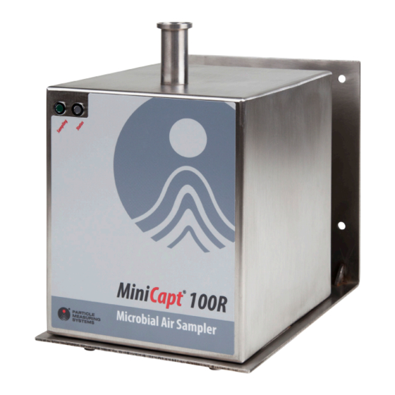
MiniCapt Remote Microbial Air Sampler. Impactor Sampler Head Mounting Bracket Figure 1-1 MiniCapt 100R Microbial Figure 1-2 MiniCapt 100R Microbial Air Sampler Air Sampler and mounting bracket with BioCapt Impactor sampling head and mounting bracket MiniCapt Remote Microbial Air Sampler Operations Manual Page 1-1... -
Page 15: Fluid-Dynamic System Characteristics
Chapter 1 Introduction Fluid-Dynamic System Characteristics Fluid-Dynamic System Characteristics The MiniCapt Remote Microbial Air Sampler uses a rotary blower that is able to sample a constant flow of 25 L/min, 50 L/min or 100L/min and is controlled by a mass flow controller. -
Page 16: Physical Description
Physical Description Chapter 1 Introduction Physical Description Front Status LED Sampling LED Figure 1-3 LEDs on the front of a MiniCapt Remote Microbial Air Sampler LEDs Two LEDs are located near the top of the front side of the MiniCapt Remote Microbial Air Sampler chassis (see Figure 1-3): •... -
Page 17: Bottom
Chapter 1 Introduction Physical Description Bottom The ports and connectors on the bottom of the MiniCapt Remote Microbial Air Sampler’s chassis are shown in Figure 1-4. Exhaust Port Ethernet Compressed Connector Gas Port Compressed Gas Power Solenoid Connector Connector Figure 1-4 Bottom view of the MiniCapt Remote Microbial Air Sampler All connectors are found on the bottom of the unit’s chassis (see Figure 1-4), including: •... -
Page 18: Specifications
Specifications Chapter 1 Introduction Specifications Table 1-1 MiniCapt Remote Microbial Air Sampler Specifications 100R Sampling flow rate 25 Liters/minute 50 Liters/minute 100 Liters/minute Modbus TCP Communication Enclosure: 7.2 x 5.9 x 6.3 in (18 x 15 x 15 cm) Dimensions (h, w, d) Weight 7.4 lb (3.4 kg) without BioCapt Microbial Impactor Operating environment... - Page 19 Chapter 1 Introduction Specifications This page is intentionally left blank. Page 1-6 MiniCapt Remote Microbial Air Sampler Operations Manual...
-
Page 20: Chapter 2: Unpacking And Installation
If the shipping container is damaged, STOP unpacking and notify the shipper and Particle Measuring Systems at 1-877-475-3317, or email to support@pmeasuring.com. Follow any instructions you receive on how to proceed. -
Page 21: Accessories
Chapter 2 Unpacking and Installation Items You Need to Provide a. Refer to the actual Packing List enclosed with your shipment. Accessories If accessories are purchased, the following items may have been shipped. Table 2-2 Accessories for the MiniCapt Remote Microbial Air Sampler Accessory Part Number Isolator Kit for 25 LPM, 50 LPM... -
Page 22: Installation
Installation Chapter 2 Unpacking and Installation Installation The following instructions are included to guide you through the installation process. Please pay close attention to the NOTE, CAUTION, and WARNING texts. Installation includes the following steps: • Selecting an appropriate location (see on page 2-4) Selecting a Location... -
Page 23: Selecting A Location
Chapter 2 Unpacking and Installation Installation Selecting a Location When choosing the location for the MiniCapt Remote Microbial Air Sampler(s), consider the following bulleted list of suggestions to improve the utility of the unit. • Sample Point Position the sampler to ensure that the BioCapt Impactor sampling head is pointed toward the airflow. -
Page 24: Positioning Or Mounting The Unit
Installation Chapter 2 Unpacking and Installation • Environmental conditions The unit should be located in an environment consistent with its temperature, humidity, altitude, and other relevant specifications. • Electromagnetic interference The unit should be located away from strong electromagnetic fields. Positioning or Mounting the Unit The MiniCapt Remote Microbial Air Sampler can be mounted to a flat surface with a mounting bracket that attaches to the bottom of the sensor’s chassis with... -
Page 25: Installing The Electronics Enclosure
Chapter 2 Unpacking and Installation Installation Installing the Electronics Enclosure The MiniCapt Remote Microbial Air Sampler: • Is designed to be mounted to a wall or other vertical surface that can support 10 lb (4.5 kg). • Must be installed by qualified personnel. ®... -
Page 26: Recommended Fasteners
Connecting the MiniCapt to an Ethernet Network Chapter 2 Unpacking and Installation Recommended Fasteners • Metal studs Expanding metal screws or butterfly bolts. • Wood studs Minimum of 5 cm long metal fasteners with self-tapping threads suitable for soft material. •... -
Page 27: Powering The Minicapt
Chapter 2 Unpacking and Installation Powering the MiniCapt Powering the MiniCapt NOTE: The main power disconnect is the power cord, so ensure that the power cord plug is easily accessible. Connecting Power There is no ON/OFF button on the MiniCapt Remote Microbial Air Sampler. Plugging the unit into power turns it on. -
Page 28: Chapter 3: Ethernet Communications Overview
Ethernet Addressing Basics Particle Measuring Systems instruments must be properly configured for Ethernet communications in order to work. There are multiple numeric parameters required to properly configure an instrument and a small error in one or more of these parameters can result in no communications, or worse—sporadic communications. -
Page 29: Network Mask
172.31.255.255 192.168.0.0 192.168.255.255 C (16 Bit Range) Particle Measuring Systems provides a unique default address in the Class A range for every instrument. Whenever the instrument is set to default parameters or factory defaults, this address is restored. Network Mask The network mask is used to discern the network portion of the IP address from the location portion. -
Page 30: Gateway Address
For all Particle Measuring Systems instruments, this is done at least once when the instrument boots. In some newer instruments, the MAC address is announced to the switch or router every time a network connection is detected. -
Page 31: Static Ip Addresses Versus Dhcp Addresses
Chapter 3 Ethernet Communications Overview Static IP Addresses versus DHCP Addresses All Particle Measuring Systems instruments use a static IP address. This means the address is predefined. The address is used to identify the instrument when data is collected. In contrast, many computers use a dynamic IP address (i.e., DHCP or Dynamic Host Configuration Protocol). -
Page 32: Figure 3-2 Example For Ping Test
Chapter 3 Ethernet Communications Overview 2 Verify the device can talk using PING. a. Open a command shell on a PC, and type PING aaa.bbb.ccc.ddd where aaa.bbb.ccc.ddd is the address of the device. If there is no response, then there is an addressing problem. Figure 3-2 Example for PING test b. -
Page 33: Instrument To Laptop Ethernet Setup
There are two ways to establish a direct Ethernet link between a laptop (or other PC) and a Particle Measuring Systems instrument. The first way is to modify the PC Ethernet settings to work with the existing instrument settings. The second way is to modify the instrument settings to work with the existing PC settings. -
Page 34: Figure 3-4 Local Area Connection Properties Window
Chapter 3 Ethernet Communications Overview a.2 Right click on the adaptor, and then select Properties. A window similar to that shown in Figure 3-4 3-7 should be on page displayed Figure 3-4 Local Area Connection Properties window b. Select the item Internet Protocol (TCP/IP). If given an option for Version 4 or Version 6, select the one titled Internet Protocol Version 4. -
Page 35: Method 2: Modifying The Settings On An Instrument
Chapter 3 Ethernet Communications Overview Figure 3-5 Internet Protocol (TCP/IP) Properties window with IP address and subnet mask defined d. Record the existing settings on the Internet Protocol (TCP/IP) Properties window. These settings will need to be restored after the instrument communication session is complete. - Page 36 Chapter 3 Ethernet Communications Overview APIPA allows a PC to automatically assign itself an IP address even when no DHCP server is present to provide an address to the PC. Translated this means that by assigning the right address to an instrument, it will talk one to one with a Windows machine without setting an address on the Windows machine.
- Page 37 Chapter 3 Ethernet Communications Overview This page is intentionally left blank. Page 3-10 MiniCapt Remote Microbial Air Sampler Operations Manual...
-
Page 38: Chapter 4: Configuring For Ethernet
Chapter 4 Configuring for Ethernet Configuration Basics Configuration is the process of entering Ethernet settings that will allow the MiniCapt Remote Microbial Air Sampler to communicate over a specific network. Appropriate Ethernet settings are required for the Modbus TCP protocol (see Chapter 5, “Modbus Protocol.”)for use with third party applications. -
Page 39: Setting Configuration Addresses For Ethernet
Chapter 4 Configuring for Ethernet RS-232 Cable A RJ-12 to RS-232 Serial Adapter Cable (PMS-CD1995) can be purchased from Particle Measuring Systems. The wiring for this cable is as follows: Table 4-1 RS-232 Pin Outs (RJ-12 jack) Pin 1 Pin 2 Transmit ®... -
Page 40: Configuration Commands
Chapter 4 Configuring for Ethernet When communications are established with the unit, a prompt appears. Enter the Configuration commands (see “Configuration Commands” below) to set the following addresses: Set the IP address. Set the Net mask. Set the gateway address. Enter the “write”... - Page 41 Chapter 4 Configuring for Ethernet Set gat(eway) aaa.bbb.ccc.ddd The gateway address is used when communicating across different networks. This command sets the gateway address in a form of aaa.bbb.ccc.ddd. Each three-digit series is a value of 0-255 separated by a period (.) character. Use gateway 000.000.000.000 if no gateway device is available on the network.
-
Page 42: Viewing Configuration Settings
Chapter 4 Configuring for Ethernet Write Saves the most recent changes. You must send this command after setting up the instrument, or your parameters will be lost when the sensor is de-energized. NOTE: When the programming is complete, record these settings for future reference. -
Page 43: Connecting The Ethernet Cable
Chapter 4 Configuring for Ethernet Connecting the Ethernet Cable The MiniCapt Remote communicates with a third party Modbus application by means of a CAT 5 UTP Ethernet cable. The sampler is designed to work best with a CAT 5 UTP cable. -
Page 44: Chapter 5: Modbus Protocol
Chapter 5 Modbus Protocol Communications with the MiniCapt Remote Microbial Air Sampler are available via Modbus TCP. The instrument presents a single TCP/IP Ethernet connection at port 502 using the standard Modbus protocol. Two specification documents were used in the development of the Modbus interface: •... - Page 45 Chapter 5 Modbus Protocol Modbus Overview The map delineates three types of register assemblies: 1 Unary: an individual register 2 Dual: a register pair used for a 32 bit representation 3 String: a group of registers containing ASCII bytes There is a setting available that toggles the interpretation of selected dual-register values.
-
Page 46: Input Registers
Input Registers Chapter 5 Modbus Protocol Input Registers The input registers are in two sections: Configuration and Data. The Configuration section description begins on this page. The Data section description begins on page 5-5. Configuration Section The Configuration section contains: •... -
Page 47: Table 5-1 Input Register - Configuration
Chapter 5 Modbus Protocol Input Registers 30013 - 30014: Dual-register representation of the nominal flow rate in Flow Rate liters per minute. Can be integer or float depending on mode selected. The integer representation uses the scale factor from register 30011. Processed as a variable but fixed to a value of 0 for 30015:... -
Page 48: Data Section
Input Registers Chapter 5 Modbus Protocol Data Section The Data section contains: • Calibration Date • Serial Number • Device Status • Device State • Number of data samples in queue • Sample Data information The Data section starts with what would have normally been considered configuration information - calibration date and serial number. - Page 49 Chapter 5 Modbus Protocol Input Registers 30215: A value of zero is identical to no data available (same meaning as coil 00/02 read as zero). Number of Data Samples in the Queue The queue size setting will determine if the data register section shows real-time data or stored data.
-
Page 50: Table 5-2 Input Register - Data Packet
Input Registers Chapter 5 Modbus Protocol 30229 - 30234: Dual-register representation of the data packet analog value. Can be integer or float depending on mode selected. The Analog Data integer value represents the total averaged Flow, total Volume and total Duration for the data processed thus far in the recipe. - Page 51 Chapter 5 Modbus Protocol Input Registers Table 5-2 Input Register – Data Packet (Continued) Input Registers Description (Data Packet) Comment Notes 30226 unary Location Location value 30227 unary Number Particle Channels Fixed number of sizes 0 fixed 30228 unary Number Analog Channels Fixed number of analogs 3 fixed 30229...
-
Page 52: Holding Registers
Holding Registers Chapter 5 Modbus Protocol Holding Registers Like the coils, spares are in place between the “standard” registers and those that are designated as specific/optional. There are no specific/optional coils defined for the MiniCapt. If the sample setting holding registers are sent while the unit is sampling, it will ignore the new settings until the next sample set is executed. -
Page 53: Coils
Chapter 5 Modbus Protocol Coils Coils Like the holding registers, spares are in place between the “standard” coils and those that are designated as specific/optional. There are no specific/optional coils defined for the MiniCapt. The data collection coil will enable/disable sampling. 00/01: Read: 1=Sampling Enabled, 0=Sampling Disabled. -
Page 54: Table 5-4 Coils
Coils Chapter 5 Modbus Protocol Sample Volume Mode. The sample volume control will change how the unit 00/09: controls sampling. If set, holding register 40003 will contain the sample volume to be processed multiplied by a factor of 100. If clear, holding register 40003 will contain the sample interval to be processed in seconds. -
Page 55: Data Register Processing
Chapter 5 Modbus Protocol Data Register Processing Data Register Processing The unit can provide real-time data or queued data or both. There is only one section of input registers assigned for data to handle this information. If the unit is setup to queue data then the data shown is the oldest data in the queue. The data available coil (00/02) will be set on a read if there is data in the queue. -
Page 56: Associated Values For Specific Registry Entries
Associated Values for Specific Registry Entries Chapter 5 Modbus Protocol Associated Values for Specific Registry Entries Table 5-5 Associated values for specific registry entries 0x0001 Data Collection Matches the common coil settings Device Status Entries 0x0002 Data Available 0x0004 Data Clear 0x0008 Reset 0x0010... - Page 57 Chapter 5 Modbus Protocol Associated Values for Specific Registry Entries This page is intentionally left blank. Page 5-14 MiniCapt Remote Microbial Air Sampler Operations Manual...
-
Page 58: Chapter 6: Accessories
Chapter 6 Accessories Accessories for the MiniCapt Remote Microbial Air Sampler are available in the following kits: • Compressed Gases Sampling Kit (see on page 6-4) Compressed Gases Kit • Isolator Monitoring Kit (see on page 6-6) Isolator Monitoring Kit •... -
Page 59: Install The Agar Plate
Chapter 6 Accessories Install the Agar Plate Install the Agar Plate The following instructions include the steps for installing an agar plate on the MiniCapt Remote Microbial Air Sampler. You can assemble the components of a kit without installing an agar plate, if desired. >>... -
Page 60: Figure 6-4 Agar Plate On The Plate Holder With Agar Plate Lid Still In Place
Install the Agar Plate Chapter 6 Accessories Place the agar plate on the plate holder (see Figure 6-4 Agar plate on the plate holder with agar plate lid still in place Figure 6-4 Remove the lid from the agar plate. Replace the sampler head on top of the agar plate (see Figure 6-5 Sampler head re-installed over the agar plate... -
Page 61: Compressed Gases Kit
Chapter 6 Accessories Compressed Gases Kit Compressed Gases Kit The Compressed Gas Kit can be placed on the MiniCapt Remote Microbial Air Sampler after removing the BioCapt Impactor sampling head and replacing it with the base provided in the kit. There are two Compressed Gas Kits: •... - Page 62 Compressed Gases Kit Chapter 6 Accessories >> To install the Compressed Gas Kit on the MiniCapt: Follow the instructions in on page 6-2 for installing the agar Install the Agar Plate plate. Refer to on page 6-4 as needed for the following steps. Figure 6-6 Install the Dual Connection BioCapt Impactor Head over the agar plate.
-
Page 63: Isolator Monitoring Kit
Chapter 6 Accessories Isolator Monitoring Kit Isolator Monitoring Kit The Isolator Monitoring Kit can be used to sample in the isolator. There are two Isolator Monitoring Kits: • 25/50 LPM units • 100 LPM unit NOTE: For correct sampling, ensure the correct kit for required flow rate is used. -
Page 64: Remote Sampling Isp Kit
Remote Sampling ISP Kit Chapter 6 Accessories Remote Sampling ISP Kit The Remote Sampling ISP Kit can be used to attach the MiniCapt Remote Microbial Air Sampler to an ISP (Isokinetic Sampling Probe). An isokinetic sampling probe is used to capture particles passing through a defined area for a defined time without disturbing the particle paths. - Page 65 Chapter 6 Accessories Remote Sampling ISP Kit >> To install the Remote Sampling ISP Kit on the MiniCapt: Place the over the agar plate on the MiniCapt. Dual Connection BioCapt Impactor over the agar plate on the MiniCapt Figure 6-10 Dual Connection BioCapt Impactor Place the on top of the Remote Sampling Adapter...
-
Page 66: Chapter 7: Maintenance And Performance Checks
Chapter 7 Maintenance and Performance Checks There are no user-serviceable items in the MiniCapt Remote Microbial Air Sampler. You can, however, clean the sampler’s housing, replace batteries, repair or replace cables and cable connectors. Cleaning the Sampler’s Housing WARNING Disconnect the power cord from its power source. The sample probe must be capped before the instrument is sterilized by means of liquid, spray, or mist. -
Page 67: Performance Checks
Chapter 7 Maintenance and Performance Checks Performance Checks Performance Checks Complete the following procedures to verify that your instrument is operating properly. Airflow Rate Check The sample flow is factory-set using a critical orifice and is not adjustable. If the flow drops by 15% there may be a blockage in the critical orifice or inlet jet. -
Page 68: Chapter 8: Cleaning Procedures
The below procedure describes the recommended practices for MiniCapt and BioCapt impactor heads and related cleaning accessories. Particle Measuring Systems assures that all delivered products and materials are tested and cleaned according to the most demanding cleanroom requirements. In addition, the presence of manufacturing and/or handling residues may occur for 316L Stainless Steel items such as MiniCapt or BioCapt impactor heads which undergo a highly complex machining process. -
Page 69: Runtime Cleaning Guidelines
The above procedures are intended to provide general guidelines and may not be applicable in some specific manufacturing scenarios. For more information, contact your Particle Measuring Systems local representative or go to www.pmeasuring.com. Page 8-2... -
Page 70: Chapter 9: Troubleshooting
Chapter 9 Troubleshooting Use this chapter to help troubleshoot issues with the MiniCapt Remote Microbial Air Sampler, such as power issues, communication messages, errors and leaks. Troubleshooting Matrix Problem Symptoms Possible Cause No Power No lights Power supply not Check the seating of the power connected to a supply cable in the unit. -
Page 71: Airflow Rate Errors
Chapter 9 Troubleshooting Airflow Rate Errors Airflow Rate Errors As a result of the performance check procedure (see Chapter 6, “Maintenance and Performance Checks.”), the flow rate at the sensor’s inlet should be the following: • 25 LPM + 5% •... -
Page 72: Appendix A: International Precautions
Appendix A International Precautions Hazard Symbols The meaning of hazard symbols appearing on the equipment is as follows: Symbol Nature of Hazard Attention, consult accompanying documents. Dangerous High Voltage Symboles de risque Des symboles représentant les risques sont placés sur l'appareil. Leur signification est la suivante: Symbole Nature du risque... -
Page 73: Warnschilder
Appendix A International Precautions Warnschilder Warnschilder Die, an dem Gerat angebrachten Warnschilder haben folgende Bedeutungen: Symbol Gefahrenart Achtung! In den beiliegenden Unterlagen nachschlagen Achtung Hochspannung Simboli di pericolo Il significato dei simboli di pericolo che appaiono sugli strumenti il seguente: Simbolo Natura del pericolo Attenzione. -
Page 74: Appendix B 有毒或有害的物质和元素
Appendix B 有毒或有害的物质和元素 有毒或有害的物质和元素 Part Name 铅 汞 镉 六价铬 多溴联苯 多溴联苯醚 部件名称 (Pb) (Hg) (Cd) (Cr(VI)) (PBB) (PBDE) 电源供应 印刷电路装配 机械部件 电缆 机电 O: 表示用于部件的所有同族物质中所含的有毒或有害物质低于SJ/T11363-2006规定的限 度要求。 X: 表示用于部件的至少一种同族物质中所含的有毒或有害物质高于SJ/T11363-2006规定 的限度要求。 MiniCapt Remote Microbial Air Sampler Operations Manual Page B-1... - Page 75 Appendix B 有毒或有害的物质和元素 This page is intentionally left blank. Page B-2 MiniCapt Remote Microbial Air Sampler Operations Manual...