Advertisement
Quick Links
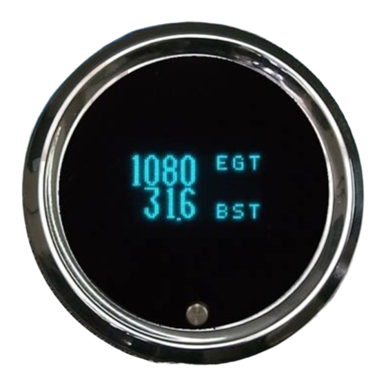
VACUUM/BOOST PRESSURE, TEMP, and EGT GAUGE
SENSOR CONNECTION:
The vac./boost sensor has 1/8" NPT on the end which can be treaded into the intake
track, or into a pipe adapter with a barbed fitting and vacuum line to T-into a convenient
vac./boost lines. The sensor should be connected to the control unit as follows:
RED
WHITE
BLACK
The temperature sensor is 1/8" NPT. Senders can be mounted into the oil pan (a nut or
collar may need to be welded to the pan) or T'd into an oil cooler line. These senders have a
tapered self-sealing thread. The threads should all be cleaned before installation and no tape
or thread sealant should be used on the threads. Make sure that the sender tip can get into the
coolant flow. If the sender cannot ground through its threads then a ground will have to be
connected to the sender case. Connect the supplied spade terminal to the top of the sensor and
wire to the control unit TEMP terminal.
The EGT sensor will need to be mounted in the exhaust system close to the engine. Drill
and weld the supplied bung to the exhaust. Connect the red wire to the control unit EGT RED
terminal. Connect the yellow wire to the control unit EGT YEL terminal. Be careful to route the
sensor cable away from any power or spark plug wires. Wires routed along side the sensor
cable can cause interference and incorrect readings. Do NOT extend the EGT wires with
normal wire, this will also cause incorrect readings and operation.
Only use Dakota Digital sensors, sending units from other manufacturers may cause
incorrect readings.
1
ODYR-25-1 & SLX-25-1 rev. A
-
Connect to control unit PWR terminal
-
Connect to control unit BOOST terminal
-
Connect to control unit GND terminal
MAN# 650051-A
Advertisement

Summary of Contents for Dakota Digital Odyssey ODYR-25-1
- Page 1 Do NOT extend the EGT wires with normal wire, this will also cause incorrect readings and operation. Only use Dakota Digital sensors, sending units from other manufacturers may cause incorrect readings. MAN# 650051-A...
-
Page 2: Gauge Setup
Mounting: The gauge requires a round hole 2-1/16” in diameter. It should be inserted into the opening from the front and the U-clamp will be installed from the back. Tighten the two nuts on the U-clamp so that the gauge is secure. Gauge depth to the back of the case is 1”. Gauge depth including the mounting studs is 1-7/8”. - Page 3 BOOST CALIBRATION When “BST CAL” is displayed press and hold the button until the display dims, then release the button. Now the two calibration menus can be accessed. The supplied boost sensor measures atmospheric pressure. The controller then calculates appropriate boost or vacuum readings.
- Page 4 TEMP UNIT The temp unit is set by holding the switch when the “TEMP UNIT” message is displayed until the display dims and is released. The current unit will be displayed, F or C. Press and release the switch to toggle the unit. When the desired unit is displayed, press and hold the switch until the display dims to save the value.
-
Page 5: Operation
For higher current buzzers, lights, or solenoids, a relay will need to be used to switch the indicator on. Dakota Digital’s RLY-1 30A relay may be used for this. One of the coil wires should be connected to 12 volts and the other coil wire connected to the WRN1 terminal. When the gauge is outside its limits, the relay will turn on. - Page 6 GAUGE RANGE AND DISPLAY: The vac/boost reading will display pressures from 22 inHg to 85 psi at sea level. There is a separate boost warning output, WRN2, that is adjustable and can be used to trigger events based on boost pressure. The boost warning levels are adjustable along with the update rate. A negative sign indicates vacuum and the decimal point is also absent, below are some sample readouts.
-
Page 7: Troubleshooting Guide
Troubleshooting guide. Problem Possible cause Solution Gauge will not light up PWR terminal does not have Connect to a location that has power. power. GND terminal is not getting Connect ground to a different location. a good ground. Display harness is unplugged. Seat connectors in tightly at both ends. -
Page 8: Service And Repair
Any action for breach of any warranty hereunder, including any implied warranty of merchantability, must be brought within a period of 24 months from date of original purchase. No person or representative is authorized to assume, for Dakota Digital, any liability other than expressed herein in connection with the sale of this product.