
Summary of Contents for Duplo DBM-150
- Page 1 INSTRUCTION MANUAL STAPLER FOLDER DBM-150 TRIMMER DBM-150T Original instructions Be sure to read this manual prior to use. Please leave this manual at the site of use for easy reference.
- Page 2 Introduction Thank you for purchasing a Duplo product. Be sure to read this manual prior to using the product. After reading, leave the manual at the site of use for easy reference whenever questions related to the product arise in the future.
-
Page 3: Safety Precautions
Safety Precautions Safety Precautions In this manual, operations and handling of the unit which are hazardous are described using the following marks to prevent personal injury or property damage to the user and others. Ignoring this mark could result in the possibility of serious injury or even death. -
Page 4: Operating Environment
Safety Precautions Operating Environment Operate this unit in the following environment. • where the temperature range is between 5 and 35°C (-10 to +50°C in storage) • where the humidity range is between 20 and 85% RH (10 to 90% RH in storage, however no condensation) •... -
Page 5: Maintenance / Other
Safety Precautions Maintenance / Other Do not damage the power cord or power plug. Do not scratch, alter, bend, twist, pull or place heavy objects on the power cord or power plug. This could result in damage, a fire or an electrical shock. Do not touch the power switch with wet hands. -
Page 6: Warning / Caution Labels
Safety Precautions WARNING / CAUTION Labels "WARNING" and "CAUTION" labels are pasted on the machine to ensure user safety. Do not remove or change them. When the labels become dirty or are lost, be sure to contact your dealer for a new one. For North America Do not sit on the stacker tray. - Page 7 Safety Precautions For EU Do not sit on the stacker tray. Do not push the stacker tray. Do not put a heavy load on the stacker tray.
-
Page 8: Table Of Contents
When the folding position is not straight ..2-17 1. Features ........... 1-1 7-2. Adjusting the roller gap ........2-18 1-1. The features of the DBM-150 ......1-1 7-3. Adjusting trimming misalignment ....2-19 1-2. The features of the DBM-150T ......1-2 7-4. - Page 9 Contents 3-1. Troubleshooting for the DBM-150 ....5-7 3-2. Troubleshooting for the DBM-150T ....5-10 3-3. Common troubleshooting for the DBM-150 and DBM-150T ............5-10 Chapter 6 Appendix Specifications ..........6-1...
- Page 10 Memo Contents viii...
-
Page 11: Chapter 1 Before Operation
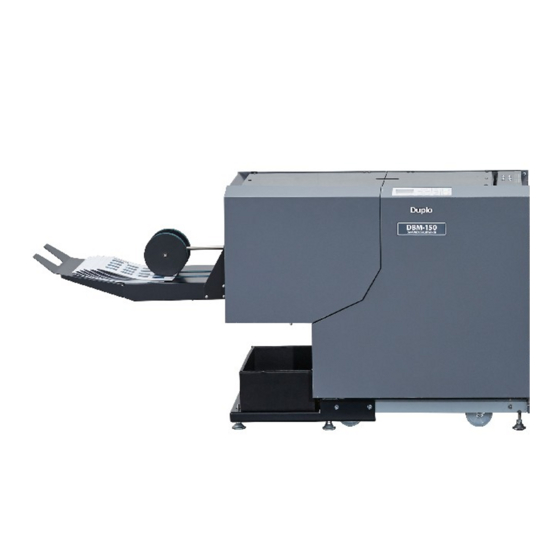
Chapter 1 Before Operation Features 1-1. The features of the DBM-150 • The DBM-150 is a stapler folder that can make a booklet in two binding modes: saddle staple and fold (no staple, fold only). Saddle staple Fold You can also make a booklet in other modes using the option kit below. -
Page 12: The Features Of The Dbm-150T
1-2. The features of the DBM-150T The DBM-150T is a trimmer and is connected to the stapler folder DBM-150. The DBM-150T trims the fore- edge of a booklet made by the DBM-150. As a downstream unit of the DBM-150, this machine starts or stops in conjunction with the DBM-150. -
Page 13: Names And Functions Of Components
Chapter 1 Before Operation Names and Functions of Components When using both the DBM-150 and the DBM150T, each machine is connected with each other as shown in the figure below. When not using the DBM-150T, the belt stacker is connected to the DBM-150. -
Page 14: External Parts
Chapter 1 Before Operation 2-1. DBM-150 external parts [10]... - Page 15 Chapter 1 Before Operation Name Function Top cover Cover for ensuring user safety. This machine will not operate if open. Control panel Use this panel to enter information to operate the machine. (p.1-11) Folding misalignment adjustment Adjusts folding misalignment. (p.2-17) Inlet for stacker connector Insert the connector of the belt stacker to this inlet.
-
Page 16: Internal Parts
Chapter 1 Before Operation 2-2. DBM-150 internal parts [12] [13] [14] [15] [13] [12] [11] [10]... - Page 17 Chapter 1 Before Operation Name Function Side guide Aligns the sides of paper. (p.2-12) When the SXS MODIFICATION KIT (option) is attached to this machine, the shape of the side guide is different. (p.3-4) Conveyance roller Conveys paper. (p.4-1) When the SXS MODIFICATION KIT (option) is attached to this machine, there is no conveyance roller.
-
Page 18: Dbm-150T
Chapter 1 Before Operation 2-3. DBM-150T Name Function Top cover Cover for ensuring user safety. This machine will not operate if open. Scrap box Scrap paper of trimmed booklets is ejected to this box. Trimming stopper adjustment Adjusts the position of the trimming stopper to correct trimming misalignment. -
Page 19: Belt Stacker
Chapter 1 Before Operation 2-4. Belt stacker Name Function Belt stacker Booklets are ejected here from the DBM-150 or the DBM-150T. Conveyance belt Conveys paper. (p.4-1) Paper guide roller Holds a booklet as an aid for the belt stacker. (p.2-11)(p.2-20) Ejection tray Ejected booklets are stacked on this tray. -
Page 20: Accessories
Chapter 1 Before Operation 2-5. Accessories Name Manual feed guide F Attach the guide to the operator's side of the manual feed inlet/paper feed inlet with the magnet and move them according to a paper size. (p.3-15) Manual feed guide B Attach the guide to the non-operator's side of the manual feed inlet/ paper feed inlet with the magnet and move them according to a paper size. -
Page 21: Names Of Control Panel
Chapter 1 Before Operation Names of Control Panel [12] [11] [10] Name Function LCD display Displays menus and error messages. key: press to change setting values or to select setting items. key: press to change the settings and values. (fine adjustment) key Displays the fine adjustment menu. -
Page 22: Screen Descriptions
DBM-150. The paper size available on the upstream unit is automatically registered on the DBM-150 memory and the memory No. whose paper size is the same as you have selected on the upstream unit is automatically called. -
Page 23: Menu List
Trimming On The setting menu items are as follows. When the sheet feeder or the DFC-100 is connected to the DBM-150 as a upstream unit, the setting menu is not displayed. Make settings for the following items on the upstream unit. - Page 24 297.0 Width 210.0 Custom Width 210.0 Length 297.0 Width 210.0 This is displayed only when the binding mode is set to [Saddle/Fold] Setting or [Fold] and the DBM-150T is connected to the DBM-150 as a downstream Trimming On unit. 1-14...
- Page 25 Step Trim* When [Trimming On] has been selected in the setting menu, specify whether to trim paper in the step mode. [ON]/[OFF] Default: [OFF] * Displayed only when the DBM-150T is connected to the DBM-150 as a downstream unit. 1-15...
- Page 26 Step Trim Function T Conv.Stop Step Trim This is displayed only when the sheet feeder is connected to the DBM-150 as a upstream unit. Function Buzzer Set This is displayed only when the DBM-150T is connected to the DBM-150 Function as a downstream unit.
- Page 27 Chapter 1 Before Operation 4-2-3. Fine Adjustment Menu The fine adjustment menu is displayed if you press the key with the top screen displayed. fine adjustment Adjustment Back Guide Side Guide Use the fine adjustment menu to fine adjust stapling and folding positions while checking a finished booklet. When you press the start key of the upstream unit (when a upstream unit is connected) or the key of this machine (when a upstream unit is not connected) with the fine adjustment menu selected, the machine...
- Page 28 Adjustment Staple Psn Fold Psn S/F Psn Adjustment Base Psn Adjustment This is displayed only when the binding mode is set to [Saddle/Fold] or [Fold] and the DBM-150T is connected to the DBM-150 as a downstream Trim Psn unit. 1-18...
-
Page 29: Options
Options 5-1. CORNER AND SIDE STAPLE KIT Name Function Side-stapling guide Attach this between the folding rollers of the DBM-150. (p.3-1) Staple guide F Attach this to the stapler unit F. (p.3-1) Staple guide B Attach this to the stapler unit B. -
Page 30: Sxs Modification Kit
Upper conveyance unit Attach this to the DBM-150. (p.3-7)(p.3-11) Lower conveyance unit (L) Attach this to the DBM-150 when stapling paper whose length is 279 mm/10.98 inches or more or the CORNER AND SIDE STAPLE KIT is attached. (p.3-7) Lower conveyance unit (S) Attach this to the DBM-150 when stapling paper whose length is less than 279 mm/10.98 inches. - Page 31 Function Side guide B (L) When stapling paper whose length is 279 mm/10.98 inches or more or when the CORNER AND STAPLE KIT has been attached to the DBM-150, attach this to the non-operator’s side of the DBM-150. (p.3-4) Side guide F (L) When stapling paper whose length is 279 mm/10.98 inches or more or...
-
Page 32: Workflow
The flowchart below describes basic operating procedures. See the text and the relevant pages. Turn on the power (p.2-1) Make settings on the control panel (p.2-2) Preparing the DBM-150 (p.2-5) Prepare the upstream unit (p.2-11) Perform operations step by step (p.2-11) -
Page 33: Chapter 2 Basic Operation
Make sure that the power plug is connected to the wall socket. 1-1. Turning on the power When the upstream unit is not connected to the DBM-150 Set the main power switch of the DBM- 150 to "l." Set the power switch of the DBM-150 to "l."... -
Page 34: Turning Off The Power
No. that can be overwritten and make settings following the procedures below. When the sheet feeder or the DFC-100 is connected to the DBM-150 as a upstream unit, make settings of bookletmaking on the upstream unit. -
Page 35: When Setting The Custom Size
Chapter 2 Basic Operation Press the key or key to select [01], Setting then press the key. Saddle/Fold Press the key. The binding mode will be selected. Setting Press the key or key to select Saddle/Fold [Saddle/Fold], then press the key. - Page 36 Chapter 2 Basic Operation The [Length] screen will be displayed. Length Press the key or key to select a digit 297.0 whose value you want to specify. Press the key or the key to specify a Length value. 290.0 Press the key.
-
Page 37: Preparing The Dbm-150
Chapter 2 Basic Operation Preparing the DBM-150 3-1. Adjusting the position of the stapler Move the stapler unit and the clincher according to the stapling width. Set the main power switch of the this machine to “O.” Do not touch the power switch with wet hands. - Page 38 Chapter 2 Basic Operation Stapler unit B Loosen the stapler fixing knob of each stapler unit. Remove each stapler unit from the machine. Stapler xing knob Stapler unit F Using the supplied hexagonal wrench, loosen the clincher fixing screws. Do not disassemble the product more than needs.
- Page 39 Chapter 2 Basic Operation F side B side Move the clincher according to the scale on the label. When moving the clincher, hold each side of the clincher. Align the edge of the clincher on the operator’s side with the scale. ”Stapling position”...
- Page 40 Chapter 2 Basic Operation Binding Paper width Mark on label mode (stapling width) Side staple LTR (279.4 mm 4 (258 mm (option) /11 inches) /10.16 inches) A4 (297 mm 5 (276 mm /11.69 inches) /10.87 inches) * ”1” is not for side-stapling. When attaching the stapler unit to the machine, align the notch of the stapler unit located on the non-operator’s side with the...
- Page 41 Chapter 2 Basic Operation Stapling position Stapling width is the center to center distance between the two staples. The stapling width and the stapling position are determined by a paper size. Saddle stapling and folding The stapling width is 70 mm/2.76 inches, 108 mm/4.25 inches or 160 mm/6.30 inches depending on a paper size.
-
Page 42: Adjusting The Folding Roller Gap
Chapter 2 Basic Operation 3-2. Adjusting the folding roller gap Adjust the folding roller gap according to the thickness of a booklet. If the gap is not appropriate, stripping of the cover or a paper jam may occur. While pulling the roller gap adjustment toward the inside of the machine, move the adjustment according to the thickness of the booklet. -
Page 43: Adjusting The Position Of The Paper Guide Roller
Chapter 2 Basic Operation 3-3. Adjusting the position of the paper guide roller Adjust the position of the paper guide roller so that the lead edge of the ejected booklet is slightly beyond the center of the paper guide roller as follows. When the belt stacker is connected to the DBM-150T, adjust the paper guide roller in the same way. -
Page 44: Adjusting The Guide Position
Chapter 2 Basic Operation Press the start key on the control panel of the upstream unit. A set of paper will be conveyed from the upstream unit to the stapling section and stop there. When the upstream unit is not connected to this machine, press the key of this machine and insert paper from the manual feed inlet. -
Page 45: Checking A Finished Set
Chapter 2 Basic Operation Press the key or key to change the Step Mode value. Back Guide Side Guide Press the key. The paper will be ejected to the belt stacker. Do not move the side guides and the back guide by hand during the step mode. -
Page 46: When Stapling And Folding Positions Do Not Align
Chapter 2 Basic Operation - Pressing the key moves the back guide position by approx. 0.5 mm/0.02 inch backward. - Pressing the key moves the back guide position by approx. 0.5 mm/0.02 inch forward. Press the key. The top screen will be displayed. 6-1-2. - Page 47 Chapter 2 Basic Operation 6-2-1. Moving the stapling position to align it with the folding position Adjust the stapling position. When [Side] [Corner F] [Corner B] or [Fold] is selected as a binding mode, the stapling position cannot be adjusted. When the top screen is displayed, press key on the control panel.
-
Page 48: Adjusting Stapling And Folding Positions Simultaneously
Chapter 2 Basic Operation 6-3. Adjusting stapling and folding positions simultaneously Adjust the stapling position and the folding position at the same time. Correct example The stapled/folded line is The stapled/folded line is out The stapled/folded line is at out of position and the top of position and the bottom the center of the paper. -
Page 49: Adjusting The Trimming Position (When The Dbm-150T Is Connected)
Adjusting Each Part 7-1. When the folding position is not straight When folding misalignment has occurred, adjust the folding position using the folding misalignment adjustment, which is located at the left hand side of the DBM-150. Loosen the folding misalignment adjustment. 2-17... -
Page 50: Adjusting The Roller Gap
Chapter 2 Basic Operation Paper feed direction Depending on the folding misalignment, move the folding misalignment adjustment either to the operator’s side or to the non-operator’s side. For A: Move the adjustment to the non- operator’s side. For B: Move the adjustment to the operator’s side. -
Page 51: Adjusting Trimming Misalignment
Chapter 2 Basic Operation 7-3. Adjusting trimming misalignment Do not sit on the stacker tray. Do not push the stacker tray. Do not put a heavy load on the stacker tray. When trimming misalignment has occurred, move the trimming stopper adjustment according to the state of trimming misalignment. -
Page 52: Adjusting The Belt Stacker
Chapter 2 Basic Operation 7-4. Adjusting the belt stacker Do not sit on the stacker tray. Do not push the stacker tray. Do not put a heavy load on the stacker tray. When booklet length is short or thick, booklets may jam at the infeed section of the belt stacker or may not be stacked in a row with each booklet slightly overlapped. -
Page 53: Starting Operations
Starting Operations Press the start key of the upstream unit to start binding operations. When a upstream unit is not connected to the DBM-150, press the key of this machine. Adjusting the Paper Passage Line Check that the paper passage line aligns with that of the upstream unit. - Page 54 Chapter 2 Basic Operation Press the key. The top screen will be displayed. 2-22...
-
Page 55: Chapter 3 Advanced Operation
Chapter 3 Advanced Operation Chapter 3 Advanced Operation Attaching the CORNER AND SIDE STAPLE KIT (Option) The paper size that is compatible with the CORNER AND SIDE STAPLE KIT is as follows. *Depending on system configurations, the environment under which the product can be operated and the specification may be limited. - Page 56 Engage the notch of the stapler guide F with the knob screw of the stapler unit F. When the SXS MODIFICATION KIT (option) has been attached to the DBM-150, remove the SXS stapler guides and replace them with the stapler guides supplied with the CORNER AND SIDE STAPLE KIT.
- Page 57 Chapter 3 Advanced Operation Set the binding mode to [Side], [CornerF] or [CornerB] and start binding operations. To remove the CORNER AND SIDE STAPLE KIT, reverse the procedures above. • If [U030] or [U032] is displayed on the LCD displayed when starting operations, check that the stapling guide is attached to the machine and that the folding roller gap is set to “7.”...
-
Page 58: Attaching The Sxs Modification Kit (Option)
The use of the SXS MODIFICATION KIT enables you to use a sheet feeder as a upstream unit. Depending on a paper size and the binding mode, the parts you need to attach to the DBM-150 vary as shown in the table below. -
Page 59: Preparing The Side Guide Unit
Chapter 3 Advanced Operation Corner and side staple Lower Paper length Paper width Side guide Joint bracket conveyance unit 200 to 231 mm/ 200 to 320 mm/7.87 to 12.60 inches 7.87 to 9.09 inches 2-1. Preparing the side guide unit Prepare the “side guide unit”... - Page 60 Chapter 3 Advanced Operation Attaching the joint bracket to the side guide According to the paper size used and the type of binding, assemble the side guide unit. Align the notches (2) of the joint bracket B with the shafts of the knob screws. Align each notch with the shaft in the order shown in the figure.
-
Page 61: Attaching The Lower Conveyance Unit (L) And The Side Guide Unit
Chapter 3 Advanced Operation 2-2. Attaching the lower conveyance unit (L) and the side guide unit Follow steps 1 through 8 in “3-1. Adjusting the position of the stapler” in Chapter 2. (p.2-5) Align the upper studs (2) in the infeed section with the holes (2) of the lower conveyance unit (L) to secure them with the magnet. - Page 62 Chapter 3 Advanced Operation Attach the upper conveyance unit to the bracket in the infeed section. Align the stopper of the upper conveyance unit with the cutout of the bracket on either side, then insert the upper conveyance unit into the bracket until it clicks. After inserting the unit, check that the claw projects from the cutout on each side.
- Page 63 Chapter 3 Advanced Operation Loosen the knob screws (2 each) of the side guides F and B attached to the DBM-150 to remove the side guides. Depending on the position of the side guides, you may not be able to touch the clincher fixing screws.
- Page 64 F (L) with the notches of the DBM-150. 2) Insert the front edge of the side guide F (L) under the guide of the DBM-150. 3) Align the corner of the side guide F (L) with that of the bracket for the side guide as shown in the figure.
-
Page 65: Attaching The Lower Conveyance Unit (S) And The Side Guide Unit
• When the CORNER AND SIDE STAPLE KIT he paper is attached to the DBM-150, if t width is 200 mm/7.87 inches or more, raise the upper auxiliary guides (two). Follow steps 9 through 11 in “3-1. - Page 66 Chapter 3 Advanced Operation Attach the upper conveyance unit to the bracket in the infeed section. Align the stopper of the upper conveyance unit with the cutout of the bracket on either side, then insert the upper conveyance unit into the bracket until it clicks. After inserting the unit, check that the claw projects from the cutout on each side.
- Page 67 Chapter 3 Advanced Operation Loosen the knob screws (2 each) of the side guides F and B attached to the DBM-150 to remove the side guides. Depending on the position of the side guides, you may not be able to touch the clincher fixing screws.
-
Page 68: Attaching The Sxs Stapler Guide
CORNER AND SIDE STAPLE KIT. Use the SXS stapler guides. • If you do not attach the SXS stapler guide to the DBM-150 when the stapler units F and B have been attached to the “3” position of the label, paper jam may occur. -
Page 69: Feeding Paper Manually
When the SXS MODIFICATION KIT is attached to the DBM-150, specify the number of times that you feed paper manually using the control panel of the sheet feeder or the PC CONTROLLER. - Page 70 Memo Chapter 3 Advanced Operation 3-16...
-
Page 71: Chapter 4 Cleaning The Unit
Use of other solvents may damage the rubber rollers and resin inside the machine, resulting in malfunction. 1-1. Cleaning the conveyance belt and rollers Clean the belts and rollers while turning them using a cloth moistened with alcohol. “2-2. DBM-150 internal parts” (p.1-6) “2-3. DBM-150T” (p.1-8) 1-2. Cleaning the LCD Wipe the LCD on the control panel with the dry cloth. -
Page 72: Cleaning The Sensor
Chapter 4 Cleaning the Unit 1-3. Cleaning the sensor A dirty sensor may cause misdetection. DBM-150 [1] Ejecting section (remove the ejection unit before cleaning.) ”2-1-1. Infeed section” (p.5-4) [2] Stapling section [3] Infeed section [4] Stopper section... - Page 73 Chapter 4 Cleaning the Unit DBM-150T [1] Ejecting section [2] Infeed section...
-
Page 74: Replacing The Stapler Cartridge
Chapter 4 Cleaning the Unit Replacing the Stapler Cartridge When the stapler cartridge has almost run out of stapler pins, [U020] or [U021] is displayed on the LCD display. Purchase dedicated stapler cartridge from your dealer and replace the old cartridge with a new one in a following way. -
Page 75: Chapter 5 Trouble Guide
1-1. Warning error Error Cause Solution Code U010 The top cover of the DBM-150 or the DBM-150T Close the top cover. is open. U011 The stopper cover of the DBM-150 is open. Close the stopper cover. U020 The stapler unit F is almost empty. -
Page 76: Paper Jam Error
J062 Paper or paper chips were detected at the ejecting section of the DBM-150. J063 Paper was sent from the DBM-150 at the time Decrease the processing speed. when it cannot be processed at the DBM-150T. J071 A paper jam has occurred in front of the infeed... -
Page 77: Errors Requiring A Service Call
E850 E860 E921 When the upstream unit is connected to the Turn on the power switch of the upstream unit to DBM-150, only the power switch of the DBM- operate the DBM-150. E981 to (p.2-1) 150 is turned on. E989 If the error occurs when the settings of the power switches are correct, turn off and on the power. -
Page 78: Paper Jam
If you cannot remove the paper easily, remove the stapler unit. (p.2-5) When the SXS MODIFICATION KIT is attached to the DBM-150, first remove the upper conveyance unit, then remove the paper. (p.3-8) 2-1-3. Stopper section Open the stopper cover. - Page 79 Chapter 5 Trouble Guide 2-1-4. Ejecting section Remove the stapler unit and the ejection unit. To remove the ejection unit, push the bushing on the non-operator’s side against the operator’s side as shown in the figure. Remove the paper. When attaching the ejection unit to the machine, insert the shaft to the hole of the bracket on the operator’s side and secure the shaft to the frame on the non-operator’s side.
-
Page 80: Paper Jam At The Dbm-150T
Chapter 5 Trouble Guide 2-2. Paper jam at the DBM-150T Press the key on the control panel. Paper is ejected from the machine. When the paper is not ejected, remove it by hand. -
Page 81: Troubleshooting
The paper passage line of the upstream Select [Base Psn] from the fine adjustment upstream unit do not go unit do no align with that of the DBM-150. menu on the control panel and adjust the into the infeed section of paper passage line. - Page 82 The settings of the power switch and the Check if the power switch and the main upstream unit, the DBM- main power switch of the DBM-150 are power switch of the DBM-150 are correctly 150 is not turned on. wrong.
- Page 83 When the sheet feeder is connected to the When using the setting menu in the sheet DBM-150 as the upstream unit, the setting feeder or the cover of the sheet feeder is menu is displayed on the LCD display of open, you cannot operate the machine.
-
Page 84: Troubleshooting For The Dbm-150T
(p.1-15) 3-3. Common troubleshooting for the DBM-150 and DBM-150T Condition Cause Solution Booklets are not stacked The position of the paper guide rollers is... -
Page 85: Chapter 6 Appendix
Specifications • Design and specifications are subject to change without notice. • Depending on system configurations, the environment under which the product can be operated and the specification may be limited. Model DBM-150 DBM-150T Name of product STAPLER FOLDER TRIMMER... - Page 86 Dimensions When used DBM-150: 1,010 (W) x 560 (D) x 710 (H) mm/39.76 (W) x 22.05 (D) x 27.95 (H) inches including the belt stacker DBM-150+DBM-150T: 1,421 (W) x 560 (D) x 710 (H) mm/55.94 (W) x 22.05 (D) x 27.95 (H)
- Page 87 Chapter 6 Appendix When used DBM-150 1,010 mm/39.76 inches 560 mm/22.05 inches 710 mm /27.95 inches DBM-150+DBM-150T 560 mm/22.05 inches 1,421 mm/55.94 inches 710 mm /27.95 inches Required space DBM-150 670 mm/26.38 inches 1,112 mm/43.78 inches 989 mm /38.94 inches DBM-150+DBM-150T 670 mm/26.38 inches...
- Page 88 Date : December 26, 2013 Issues by Machine : DBM-150 SxS Subject : How to use the Pressure Adjustment Unit When you get jam at the entrance section by thick paper, please change the position of the knob screw as the below picture.
- Page 89 4-1-6 Oyama, Chuo-ku, Sagamihara-shi, Kanagawa 252-5280, Japan TEL: +81-42-775-3602 FAX: +81-42-775-3606 E-mail: info@duplo.com This manual is printed on recycled paper to help protect the environment. 15Y-90063-0 13120000D...
Need help?
Do you have a question about the DBM-150 and is the answer not in the manual?
Questions and answers
Need new stitch head for my Duplo DBM-150