Table of Contents
Advertisement
Quick Links
ATN PS31
NIGHT VISION GOGGLES
OPERATOR'S MANUAL (PS31) REVISION 1 – APRIL 2020
o p e r a t o r ' s m a n u a l
Important Export Restrictions! Commodities, products,
technologies and services contained in this manual are
subject to one or more of the export control laws and
regulations of the U.S. Government and they fall under the
control jurisdiction of either the US Department of State
or the US BIS-Department of Commerce. It is unlawful
and strictly prohibited to export, or attempt to export or
otherwise transfer or sell any hardware or technical data or
furnish any service to any foreign person, whether abroad
or in the United States, for which a license or written
approval of the U.S. Government is required, without
first obtaining the required license or written approval
from the Department of the U.S. Government having
jurisdiction. Diversion contrary to U.S. law is prohibited.
Advertisement
Table of Contents

Related Manuals for American Technologies Network ATN PS31

Summary of Contents for American Technologies Network ATN PS31
- Page 1 ATN PS31 NIGHT VISION GOGGLES OPERATOR’S MANUAL (PS31) REVISION 1 – APRIL 2020 o p e r a t o r ’ s m a n u a l Important Export Restrictions! Commodities, products, technologies and services contained in this manual are subject to one or more of the export control laws and regulations of the U.S.
-
Page 2: Safety Summary
Register your product warranty online at SAFETY SUMMARY www.atncorp.com/warranty CAUTIONS • The ATN PS31 is a precision optical instrument and must be han- dled carefully at all times to prevent damage. • Do not scratch the external lens surfaces or touch them with your fingers. - Page 3 When installing the headmount over the protective mask, be careful not to break the protective mask seal around your face. • The ATN PS31 is a precision optical instrument and must be handled carefully at all times to prevent damage.
-
Page 4: Table Of Contents
TABLE OF CONTENTS SAFETY SUMMARY 2.3. Assembly and Preparation for Use 2-18 2.3.1. Unpacking 2-18 CHAPTER 1. INTRODUCTION 2.3.2. Installation of Battery 2-18 1.1. General Information 2.3.3. Installation of Eyecup 2-19 1.1.1. Scope 2.3.4. Installation and Adjustment of Headmount 2-19 1.1.2. -
Page 5: Chapter 1. Introduction
CHAPTER 1 INTRODUCTION... -
Page 6: General Information
Basic Issue Items This manual provides operation and maintenance instructions for CAGEC Commercial and Government Entity Code the Night Vision Goggles (NVG) ATN PS31 hereinafter referred to as the NVG. The NVG is a self-contained night vision device that Centimeters... -
Page 7: Glossary
1.1.5. GLOSSARY FLASHING. This is a defect in the image area of the goggles. The image appears to flicker or flash. BLACK SPOTS. These are cosmetic blemishes in the image inten- FLICKERING. See “flashing.” sifier of the NVG or dirt or debris between the lenses. GAIN. -
Page 8: Equipment Description
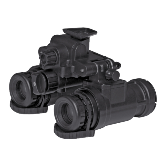
1.2. EQUIPMENT DESCRIPTION 1.2.2. LOCATION AND DESCRIPTION OF MAJOR COMPONENTS 1.2.1. EQUIPMENT CHARACTERISTICS, The NVG includes the items shown in Figure 1.1. The major compo- CAPABILITIES, AND FEATURES nents are the headmount, helmet mount, goggles, carrying case. The NVG is a hand-held, headmounted, helmet mounted night vi- a. -
Page 9: Equipment Data
f. Carrying Case TABLE 1.5. OPTICAL DATA The carrying case (Figure 1.1.) is provided for transportation and ITEM DATA protection of the goggles, headmount, battery and accessories. Magnification 1.0x Two slide keepers are provided for belt attachment and three Field-of-View 50 deg +/-2 deg D-rings for shoulder and leg strap attachment. -
Page 10: Principles Of Operation
1.3. PRINCIPLES OF OPERATION b. Auto Mode The automatic mode is different from the “IR” mode, and the auto- matic mode starts the environment detection sensor. It can detect 1.3.1. MECHANICAL FUNCTIONS environmental luminance in real time and work with reference to the The mechanical functions of the NVG allow for differences in the illumination control system. -
Page 11: Chapter 2. Operating Instructions
CHAPTER 2 OPERATING INSTRUCTIONS... -
Page 12: Description And Use Of Operator's Controls And Indicators
2.1. DESCRIPTION AND USE OF TABLE 2.1. GOGGLES CONTROLS AND INDICATORS OPERATOR’S CONTROLS AND CONTROLS AND FUNCTIONS INDICATORS INDICATORS Power Switch NOTE Turns OFF the NVGs. The NVG is a precision electro-optical instrument, so handle it carefully. If the equipment fails to operate, refer to the Trouble- Goggles activated. -
Page 13: Preventive Maintenance Checks And Services (Pmcs)
2.2. PREVENTIVE MAINTENANCE (4) Procedure Column. This column gives the procedure you must do to check or service the item listed in the Check/Service column CHECKS AND SERVICES (PMCS) to know if the equipment is ready or available for its intended mis- sion or operation. -
Page 16: Resolution Check Using The Ts-4348/Uv Test Set
2.2.2. RESOLUTION CHECK USING THE TS-4348/UV TEST SET NOTE The TS-4348/UV Test Set can be used by the operator to check the resolution of a goggles at any time. NOTE The TS-4348/UV Test Set can be used by Direct Support/Inter- mediate Level to perform the resolution testing 180 Day Ser- vice. -
Page 17: Inspection Criteria For Proper Image Intensifier Operation
(2) Turn off the room light and let your eyes adjust to the dark. NOTE For a pattern to be resolvable, three vertical bars and three (3) Turn on the test set by setting the “OFF” switch to the “ON” horizontal bars must be visible. - Page 18 There are two groups of “defects” you may encounter — opera- To check for edge glow, block out all light by cupping a hand over tional defects and cosmetic blemishes. Operational defects are an the objective lens. If the image intensifier is displaying edge glow immediate cause to reject the NVG.
- Page 19 scene you are viewing. Bright spots are acceptable if they do condition is acceptable as long as the pattern does not inter- not interfere with the operator’s ability to view the image or to fere with the operator’s ability to view the image or to perform perform the mission.
-
Page 20: Assembly And Preparation For Use
2.3. ASSEMBLY AND PREPARATION BATTERY FOR USE 2.3.1. UNPACKING The following steps must be accomplished prior to each mission where the NVG is used. (1) Check contents for completeness (see Figure 1.1.). BATTERY CAP (2) Remove carrying case. Open carrying case (Figure 1.1.), re- move NVG, and check contents for completeness. -
Page 21: Installation Of Helmet Mount To Helmet
(1) Prior to donning the headmount, loosen the four ends of the (7) Adjust chinstrap and vertical adjustment until the chin cup and chinstrap approximately two inches from the sliding bar buckles. headband are in a comfortable but firm position. NOTE (2) Snap the front and rear snaps in place. -
Page 22: Operating Procedures
(8) Disengage the nape strap latch on the left side of nape strap. STRAP TOP EDGE HELMET (9) Don the helmet. Do not fasten the helmet chinstrap. OF MOUNT MOUNT BRACKET (10) Engage the nape strap at the nape strap latch. Tension the MOUNT nape strap for a stable fit, then install and tension the helmet chin- strap. -
Page 23: Head Mounted Operation
NOTE VERTICAL The sharpest image will be observed only when the objective ADJUSTMENT LATCH lens and eyepiece lens are properly focused. (3) Rotate the diopter adjustment for the clearest view of the image intensifier screen. (4) Focus the objective lens while observing an object until the sharpest image is obtained. -
Page 24: Helmet Mounted Operation
(9) Adjust the objective lens focus (Figure 2.1.) while observing an goggles down by shaking the helmet. This places significant stress on the helmet mount. object until the sharpest image is obtained. • All Other Services — Return the helmet and the helmet mount (10) In order to adjust the interpupillary adjustment to be in line with to unit maintenance for direct mounting of the bracket via the the distance between your eyes. -
Page 25: Ir Source Operations
NOTE 2.4.3.1. Eyepiece Distance Adjustment The sharpest image will be observed only when the objective In certain circumstances you would want use only One Eye to look lens and eyepiece lens are properly focused. through the NVG. Be it to retain your natural night vision in your eye when conducting dynamic maneuvers when you have to transition (5) Rotate the diopter adjustment for the clearest view of the image between dark and lit environments. -
Page 26: Preparation For Storage
NOTE (1) Install (4) CR123 batteries into the battery holder. The purpose of the IR source is for viewing at close distances (2) Attach the battery holder to the rear of the helmet or headgear. up to 3 meters when additional illumination is needed. (3) Run the power cord from the battery holder to the NVG. -
Page 27: Operation Under Unusual Conditions
(d) Install objective lens cap. (2) Dry the goggles, mounts, and accessories after exposure to rain or high humidity and before storage. This will prevent mildew from NOTE forming in the case. • Prior to placing NVG into carrying case, ensure NVG and case (3) Do not store goggles in a wet carrying case or a wet shipping are free of dirt, dust, and moisture. -
Page 28: Chapter 3. Maintenance Instructions
CHAPTER 3 MAINTENANCE INSTRUCTIONS... -
Page 29: Lubrication Instructions
3.1. LUBRICATION INSTRUCTIONS No lubrication is required. 3.2. TROUBLESHOOTING PROCEDURES 3.2.1. TROUBLESHOOTING Table 3.1. lists common malfunctions that you may find with your equipment. Perform the tests, inspections and corrective actions in the order they appear in the table. This table cannot list all the malfunctions that may occur, all the tests and inspections needed to find the fault, or all the corrective actions needed to correct the fault. -
Page 31: Operator's Maintenance Procedures
3.3. OPERATOR’S MAINTENANCE PROCEDURES 3.3.1. CLEANING THE NVG CAUTION • The goggles is a precision electro-optical instrument and must be handled carefully. • Do not scratch the external lens surfaces or touch them with your fingers. Clean goggles with water if necessary and dry thoroughly. Clean lenses with lens paper. - Page 32 Notes Notes...
- Page 33 For customer service and technical support, please contact American Technologies Network Corp. 1341 San Mateo Avenue, South San Francisco, CA 94080 phone: 800-910-2862, 650-989-5100 www.atncorp.com ©2020 ATN Corporation...
Need help?
Do you have a question about the ATN PS31 and is the answer not in the manual?
Questions and answers