Table of Contents
Advertisement
Advertisement
Table of Contents

Summary of Contents for Christie VeinViewer Flex
- Page 1 USER GUIDE VeinViewer ® Flex 020-300020-03 Rev. 1 02-2013...
-
Page 3: Table Of Contents
INDICATIONS FOR USE ........................................1 CONTRAINDICATIONS .........................................1 CHAPTER TWO: WARNINGS AND SAFETY NOTICES ............................3 SYMBOLS DEFINITIONS .......................................3 GENERAL SAFETY AND WARNINGS ...................................5 CHAPTER THREE: VEINVIEWER FLEX DESCRIPTION ............................9 PARTS LIST ............................................9 VEINVIEWER FLEX UNIT ......................................10 CONTROL PANEL ........................................11 OPTIONAL ACCESSORIES ......................................12 CHAPTER FOUR: VEINVIEWER FLEX SETUP ..............................13... - Page 4 TABLE OF CONTENTS REMOVING THE BATTERY ......................................16 ATTACHING THE WRIST STRAP ....................................17 ATTACHING VEINVIEWER FLEX TO S-MOUNT .................................24 CHAPTER FIVE: START-UP PROCEDURE ..............................27 POWERING VEINVIEWER FLEX ....................................27 POWERING OFF VEINVIEWER FLEX ..................................28 CHAPTER SIX: OPERATING INSTRUCTIONS ..............................29 FOCUSING ..........................................29 FOCUSING PROCEDURE ......................................29...
- Page 5 TABLE OF CONTENTS CHAPTER SEVEN: LICENSE, SOFTWARE AND FIRMWARE UPGRADE .......................37 VEINVIEWER FLEX CONNECT SOFTWARE INSTALLATION .............................37 FLEX CONNECT INSTALLATION ....................................37 CONNECTING VEINVIEWER FLEX TO YOUR PC ...............................38 VEINVIEWER FLEX CONNECT IMAGE MANAGEMENT ............................38 CHAPTER EIGHT: MAINTENANCE ................................39 CLEANING ..........................................39 VEINVIEWER FLEX DISPOSAL .....................................40...
- Page 6 TABLE OF CONTENTS CHAPTER ELEVEN: TECHNICAL SPECIFICATIONS ............................55 VEINVIEWER FLEX TECHNICAL SPECIFICATIONS ..............................55 EQUIPMENT CLASSIFICATION ....................................56 CHAPTER TWELVE: LIMITED WARRANTY ..............................63 NOTES ........................................... 65 VEINVIEWER FLEX USER GUIDE 020-300020-03 Rev. 1 (03-2013)
-
Page 7: Chapter One: Introduction
CONTRAINDICATIONS patients. VeinViewer Flex is not intended to be used for imaging of veins in the eyes, in tissue differentiation, as a diagnostic device or as a form of treatment. VeinViewer Flex is not intended to be used near equipment that may emit strong magnetic fields such as MRI equipment. - Page 8 CHAPTER ONE: INTRODUCTION This page has been intentionally left blank. VEINVIEWER FLEX USER GUIDE 020-300020-03 Rev. 1 (03-2013)
-
Page 9: Chapter Two: Warnings And Safety Notices
CHAPTER TWO: WARNING AND SAFETY NOTICES Observe the safety precautions outlined in this section to obtain maximum CHAPTER TWO: WARNINGS AND SAFETY NOTICES personal safety and to protect your VeinViewer Flex. Consult accompanying documentation. Note: This symbol is blue on the product. - Page 10 This End Up established in the EU for the disposal of electronic equipment. Keep Dry Class IIa device complies with European Directive 93/42/EEC Consult operating instructions Canadian Standards Association mark. European representative VEINVIEWER FLEX USER GUIDE 020-300020-03 Rev. 1 (03-2013)
-
Page 11: General Safety And Warnings
VeinViewer Flex. Components, parts and accessories designed by other manufacturers have not been tested by Christie and are not recommended for use with VeinViewer Flex. This could result in an increase of electromagnetic emissions or... - Page 12 CAUTION: DO NOT look directly into the imaging light source and children. Failure to do so could result in a choking hazard when the VeinViewer Flex power is ON as the light output is caused by swallowing a small part that has become detached very bright.
- Page 13 CAUTION: Christie endeavors to supply a wide variety of VeinViewer Flex products to meet the needs of the end user and patient; however, interpretation and final application of VeinViewer Flex is the sole responsibility of the Health Care Professional using the device.
- Page 14 CHAPTER TWO: WARNING AND SAFETY NOTICES This page has been intentionally left blank. VEINVIEWER FLEX USER GUIDE 020-300020-03 Rev. 1 (03-2013)
-
Page 15: Chapter Three: Veinviewer Flex Description
CHAPTER THREE: VEINVIEWER FLEX DESCRIPTION VeinViewer Flex is designed for ease of use. VeinViewer Flex utilizes visible and CHAPTER THREE: VEINVIEWER FLEX DESCRIPTION Part Number Description near-infrared light for vascular imaging to illuminate and project the subcutaneous 134-002102-xx VeinViewer Flex Unit venous structure directly onto a patient’s skin. -
Page 16: Veinviewer Flex Unit
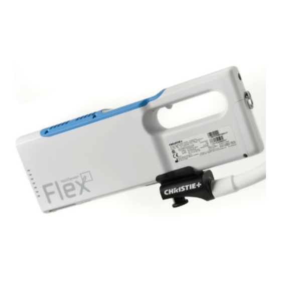
CHAPTER THREE: VEINVIEWER FLEX DESCRIPTION Controls, indicators, and features are illustrated and described below. VEINVIEWER FLEX UNIT Control Panel Power Inlet Battery Door Lock Battery Door Wrist Strap Attachment Arm Mount Attachment USB Communication Port Projection Window Fan Inlet 10 10... -
Page 17: Control Panel
CHAPTER THREE: VEINVIEWER FLEX DESCRIPTION CONTROL PANEL Power Button Status Indicator Button: Resize* Button: MaxBright* Image Capture Button* Image Mode Button Universal Fine Detail* Inverse* *Requires license upgrade to activate. See CHAPTER SEVEN: LICENSE, SOFTWARE AND FIRMWARE UPGRADES. VEINVIEWER FLEX USER GUIDE... -
Page 18: Optional Accessories
OPTIONAL ACCESSORIES Soft Travel Case (p/n 003-003983-xx) Use this optional Case for easy portability and storage of VeinViewer Flex and accessories. Car Charge Adapter (p/n 003-003984-xx): Manufacturer - Energy Access, Inc. p/n VA101214. Use the car charge adapter to charge the Battery in a vehicle. Note that the Car Charge Adapter is only for powering the Battery Charger and will not power VeinViewer Flex. -
Page 19: Chapter Four: Veinviewer Flex Setup
WARNING: Keep VeinViewer Flex dry. Do not store or operate VeinViewer Flex and components outside the The Battery is not fully charged upon delivery of VeinViewer Flex. To recommended storage or operating temperature and humidity maintain optimal performance, the Battery should always be fully range, or in dusty areas. - Page 20 Use only batteries supplied by OFF-No battery detected Christie as replacements. Green flashing-Fast charging Use only the Battery Charger provided by Christie. Other Green solid-Fully charged Battery Chargers have different voltage and terminal polarities, and their use may produce heat and smoke or even Yellow solid-Suspend: Battery Charge Interrupt result in fire or rupture.
-
Page 21: Installing The Battery
9V Inlet - Wall Outlet at approximately 4 hours. 12V Inlet - Car Outlet When powered off with the Battery installed, VeinViewer Flex enters a low-power stand-by mode, which will drain the Battery over approximately 72 hours. To maintain battery charge over extended periods, remove the Battery from the device. -
Page 22: Removing The Battery
CHAPTER FOUR: VEINVIEWER FLEX SETUP REMOVING THE BATTERY The VeinViewer Flex Battery is NOT charging the when it is installed in the battery compartment and VeinViewer Flex is plugged in via the AC Pull the battery tab directly out from the battery compartment. -
Page 23: Attaching The Wrist Strap
VeinViewer Flex. Wrist Strap. DO NOT swing VeinViewer Flex on the Wrist Strap, and keep the Wrist Strap and VeinViewer Flex clear of obstacles, as this may result in accidental impact and affect the effectiveness of VeinViewer Flex. - Page 24 CHAPTER FOUR: VEINVIEWER FLEX SETUP For your convenience, VeinViewer Flex is ready for use once the fully charged To ensure longevity of the S-Mount DO NOT bend the arm smaller Battery is installed; however, Christie recommends connecting VeinViewer Flex to than a 4 in.
- Page 25 Periodic inspection and maintenance of the arm and quick release Release the Quick Connector. should be performed to extend the efficiency and life of the arm. Contact Christie Technical Support for proper preventive maintenance procedures. VEINVIEWER FLEX USER GUIDE 020-300020-03 Rev. 1 (03-2013)
- Page 26 IV pole. WARNING: The health-care professional shall be responsible for ensuring VeinViewer Flex and mobile system (such as an IV Pole) is stable, and does not tip during set-up, operation,...
- Page 27 CHAPTER FOUR: VEINVIEWER FLEX SETUP SUPER CLAMP MOUNTING - FLAT SURFACE: CAUTION: The Super Clamp shall be mounted to a flat surface with a maximum desk thickness of 1.3 in. (3.2 cm). Turn the lever clockwise until the Super Clamp is secured to the flat DO NOT mount the Super Clamp to other surfaces beyond mounting surface.
- Page 28 CHAPTER FOUR: VEINVIEWER FLEX SETUP Pull the S-Mount Quick Release Connector back. WARNING: Use the proper mating stud associated with vertical or horizontal mounting surface orientation to avoid Place the Quick Release Connector on the mating stud on the Super possible serious injury.
- Page 29 CHAPTER FOUR: VEINVIEWER FLEX SETUP SUPER CLAMP MOUNTING - CURVED SURFACE: Remove the V-Block Flat Surface Adapter from the Super Clamp by prying it loose from the clamp. The V-Block Flat Surface Adapter stores under the Retaining Screw when not in use.
-
Page 30: Attaching Veinviewer Flex To S-Mount
V Block (stored) Super Clamp by pulling on the arm. Lever Attach the Mounting Bracket to VeinViewer Flex, securing the captive screw firmly to VeinViewer Flex using a flat head screwdriver or a coin. VEINVIEWER FLEX USER GUIDE 020-300020-03 Rev. 1 (03-2013) - Page 31 CHAPTER FOUR: VEINVIEWER FLEX SETUP Slide VeinViewer Flex into the Mounting Bracket on the S-Mount until it CAUTION: Christie endeavors to supply a wide variety of clicks into place. VeinViewer Flex products to meet the needs of the end user and patient;...
- Page 32 CHAPTER FOUR: VEINVIEWER FLEX SETUP This page has been intentionally left blank. VEINVIEWER FLEX USER GUIDE 020-300020-03 Rev. 1 (03-2013)
-
Page 33: Chapter Five: Start-Up Procedure
CHAPTER FIVE: START-UP PROCEDURE change the input connector slide the desired connector (prongs up) onto the VeinViewer Flex may be operated by AC Power Adapter or Battery power. adapter in direction shown. WARNING: VeinViewer Flex is shipped with a detachable AC Power Adapter rated specifically for VeinViewer Flex. -
Page 34: Powering Off Veinviewer Flex
The AC Power Adapter allows you to operate VeinViewer Flex continuously POWERING OFF VEINVIEWER FLEX without the use of the Battery. 1. Press and release the Power Button again to power down VeinViewer Flex. The Status Indicator will turn OFF. 2. Unplug the AC Power Adapter from the electrical outlet. -
Page 35: Chapter Six: Operating Instructions
Focus is achieved when the text around the border of the image is clear and 1. Position VeinViewer Flex so that it is perpendicular to the area to be imaged, legible (see image sample). The focusing distance for VeinViewer Flex is as shown on the following page. - Page 36 CHAPTER SIX: OPERATING INSTRUCTIONS CAUTION: Adjust the focal distance of VeinViewer Flex by moving the S-Mount arm and VeinViewer Flex together. Pulling on VeinViewer Flex alone to adjust may result in accidental dislodgment of the Mounting Bracket. 12 in (30cm) 90°...
-
Page 37: Imaging Modes
CHAPTER SIX: OPERATING INSTRUCTIONS IMAGING MODES Before proceeding to use VeinViewer Flex on the patient, ensure VeinViewer Flex is in focus, and familiarize yourself with the IMAGING MODES and IMAGING The image mode can be changed by pressing the Image Mode Button, located on FEATURES sections in this Chapter. -
Page 38: Imaging Features
CHAPTER SIX: OPERATING INSTRUCTIONS To adjust the Imaging Mode press the Mode button. VeinViewer Flex will cycle through the Modes in the following order: Universal Fine Detail* Universal in Inverse* Fine Detail in Inverse* IMAGING FEATURES Resize*: Adjusts the image to one of three different sizes. The image size can be adjusted to one of 3 sizes by pressing and releasing the f1 button located on the Control Panel. -
Page 39: Image Capture Procedure
IMAGE CAPTURE PROCEDURE Image Capture*: Captures a time stamped static image of the projected vein image and saves the image as a BMP file on VeinViewer Flex. The Press the Image Capture Button, located on the Control Panel. captured image can be transferred to a PC via a USB connection. Refer to the USB connection section in the PC Software in CHAPTER SEVEN: VeinViewer Flex DOES NOT capture patient information. -
Page 40: Projected Image Display
MESSAGE Battery Charge Level Product Name Inverse Indicator AC Power Indicator Current Mode Solid Green VeinViewer Flex is powered on Solid Red Battery Level < 25% Company Name Blinking Red (Repeatedly) Battery Level < 10% Solid Orange System Notice - See icons on image border and... -
Page 41: Software Version
CHAPTER SIX: OPERATING INSTRUCTIONS SOFTWARE VERSION The VeinViewer Flex software version is displayed VeinViewer Flex when f1 is pressed and held for 3 seconds and then released. To deactivate display window, press f1 and FIRMWARE: vXX.XX.XX hold for 3 seconds. - Page 42 CHAPTER SIX: OPERATING INSTRUCTIONS This page has been intentionally left blank. VEINVIEWER FLEX USER GUIDE 020-300020-03 Rev. 1 (03-2013)
-
Page 43: Chapter Seven: License, Software And Firmware Upgrade
DO NOT upload unauthorized files to the device. This may result in impairment of device functionality. FLEX CONNECT INSTALLATION 1. Insert included VeinViewer Flex Connect software CD, launch the CD from VEINVIEWER FLEX CONNECT SOFTWARE INSTALLATION "My Computer". 2. Double-click the VeinViewer Flex Connect installer icon to begin the installation process. -
Page 44: Connecting Veinviewer Flex To Your Pc
VeinViewer Flex USB Communication Port. Note: The first time you connect of their choice. VeinViewer Flex to your PC, the Drivers Install pop should appear. You may be prompted to install drivers. Wait until Windows reports that the device is Note: Captured Images will appear as "00000001_Year-Month-Day-T-Hr-Min-... -
Page 45: Chapter Eight: Maintenance
Failure to adhere to the following recommendations could damage VeinViewer Flex and void the warranty. This section is intended to assist you in effective cleaning of VeinViewer Flex. It is CAUTION: DO NOT spray cleaners or pour liquids directly onto also intended to protect the delicate VeinViewer Flex components during the the VeinViewer Flex surfaces. -
Page 46: Veinviewer Flex Disposal
For more detailed information about recycling of this product, please follow your institution’s guidelines or contact your waste disposal service or Christie Technical Support. VEINVIEWER FLEX USER GUIDE 020-300020-03 Rev. 1 (03-2013) -
Page 47: Chapter Nine: Service And Serviceability
The limited warranty will not apply to any product which is or has been subjected Christie Medical Holdings is committed to helping you get the greatest value from the use of your VeinViewer Flex. While VeinViewer Flex is of high quality, we do • Alteration or repair, except with authorization from Christie Medical Holdings realize that from time to time, you may need support for technical or user issues. -
Page 48: Serviceable Items By User
SERVICEABLE ITEMS BY USER Battery Door (p/n 003-003977-xx) See INSTALLING THE BATTERY in CHAPTER FOUR: VEINVIEWER FLEX SETUP. First, use a 1.5 mm Hex Driver to remove the damaged Battery Door, then: Insert Hinge Shaft in bottom of the new Battery Door. -
Page 49: Chapter Ten: Troubleshooting
Please conduct the following steps or contact your local distributor or Christie Technical Support team. 1. Inspect the VeinViewer Flex outer casing. If it does not appeared damaged, proceed to next step. If it appears damaged, DO NOT use. See CHAPTER GREEN NINE: SERVICE AND SERVICEABILITY. - Page 50 If there is any separation between the printed line and the projected line image alignment. Ensure VeinViewer Flex is perpendicular to the Alignment in ANY of the 5 horizontal and/or vertical positions, VeinViewer Flex is Test Pattern located on the inside back cover of this manual. Adjust the not within alignment specifications.
- Page 51 Battery does not have sufficient Replace with spare fully charged Battery, recharge primary Battery, or operate charge VeinViewer Flex by plugging the AC Power Adapter into a standard power receptacle. Note: If the SUSPEND or ERROR Status Indicator on the Battery Charger is lit, the battery is not charging properly.
- Page 52 VeinViewer Flex does not Status Indicator is Off (If operating by AC power) Be sure the AC Power Adapter is fully plugged into VeinViewer Flex Power Inlet. power ON (cont’d) Be sure the interchangeable input connector is properly connected to the AC AC Power Adapter is not making Power Adapter.
- Page 53 INSTRUCTIONS. Projected image does not None VeinViewer Flex is being Do not use the VeinViewer Flex outside or in direct sunlight. See the properly display veins operated outside or in direct recommended operating conditions in CHAPTER ELEVEN: TECHNICAL sunlight SPECIFICATIONS.
- Page 54 Remove the Battery from device, and inspect Battery for damage. displayed on the projected image Remove VeinViewer Flex from abnormal operating conditions, and allow VeinViewer Flex to return to normal ambient conditions for at least 15 Status Indicator is solid Fan Stall MINUTES.
- Page 55 CAUSE SOLUTION Unable to establish USB None USB connectivity issue Restart the PC. Make sure the USB Cable is properly installed to VeinViewer Flex connection to VeinViewer connected and to the USB Communication Port on the PC. Flex After connecting device, wait 30 seconds then click "Refresh" on the screen (may take several seconds).
- Page 56 If VeinViewer was not listed in the pull down menu, proceed to step below. From the windows start menu, select the "Install VeinViewer Flex Drivers" located in the "Christie" folder. Click "Next" in the "Device driver installation wizard" prompt.
- Page 57 If VeinViewer was not listed in the pull down menu, proceed to step below. From the windows start menu, select the "Install VeinViewer Flex Drivers" located in the "Christie" folder. Click "Next" in the "Device driver installation wizard" prompt.
- Page 58 Ensure you are using latest version of VeinViewer Flex Connect software. Unable to locate saved None Unable to locate default location On next image transfer, VeinViewer Flex Connect software will default to most images on PC of images recent image save location. The Christie folder may contain downloaded images from the device.
- Page 59 VeinViewer Flex Connect Disconnect VeinViewer Flex from the PC. Restart the PC. Reset VeinViewer Flex by removing the Battery and AC Power Adapter from VeinViewer Flex. Wait for 5 seconds, then reinstall the Battery and then Plug the AC Power Adapter to VeinViewer Flex.
- Page 60 CHAPTER TEN: TROUBLESHOOTING This page has been intentionally left blank. VEINVIEWER FLEX USER GUIDE 020-300020-03 Rev. 1 (03-2013)
-
Page 61: Chapter Eleven: Technical Specifications
Max 1.3 in. (32 mm) flat surface; 0.5 in. (13 mm) to Support Christie Technical Support 2.1 in. (53 mm) round surface Safety VeinViewer Flex has been tested and complies with S-Mount Maximum Vertical: 19.6 in. (49.8 cm) General Requirements for Safety per IEC 60601-1. Extension Horizontal: 25.6 in. -
Page 62: Equipment Classification
• Mode of operation of equipment - Continuous Operation. VeinViewer Flex is manufactured and sold under U.S. patent 5,969,754 and 7,239,909. FEDERAL (USA) law restricts this device to sale by, or on the order of, a physician/health-care professional. - Page 63 CHAPTER ELEVEN: TECHNICAL SPECIFICATIONS Guidance and manufacturer’s declaration - electromagnetic emissions VeinViewer Flex is intended for use in the electromagnetic environment specified below. The customer or the user of VeinViewer Flex should ensure that it is used in such an environment.
- Page 64 CHAPTER ELEVEN: TECHNICAL SPECIFICATIONS Guidance and manufacturer’s declaration – electromagnetic immunity VeinViewer Flex is intended for use in the electromagnetic environment specified below. The customer or the user of VeinViewer Flex should ensure that it is used in such an environment.
- Page 65 <5% U (>95% dip in U MAINS power quality should be that of a typical commercial or hospital and voltage variations on power environment. If the user of VeinViewer Flex requires continued operation for 0.5 cycle for 0.5 cycle IEC 61000-4-11 during power MAINS interruptions, it is recommended that the VeinViewer Flex be powered from an uninterruptible power supply (UPS) or a battery.
- Page 66 Portable and mobile RF communications equipment should be used no IEC 61000-4-6 80 MHz closer to any part of VeinViewer Flex, including cables, than the recommended separation distance calculated from the equation applicable to the frequency of the transmitter. Recommended separation distance: d=1.2 x √P from 150 kHz to 80 MHz...
- Page 67 TV broadcasts cannot be predicted theoretically with accuracy. To assess the electromagnetic environment due to fixed RF transmitters, an electromagnetic site survey should be considered. If the measured field strength in the location that VeinViewer Flex is used exceeds the applicable RF compliance level on preceding pages, VeinViewer Flex should be observed to verify normal operation.
- Page 68 Recommended separation distances between portable and mobile RF communications equipment and VeinViewer Flex VeinViewer Flex is intended for use in an electromagnetic environment in which radiated RF disturbances are controlled. The customer or the user of VeinViewer Flex can help prevent electromagnetic interference by maintaining a minimum distance between portable and mobile RF communications equipment (transmitters) and VeinViewer Flex, as recommended below, according to the maximum output power of the communications equipment.
-
Page 69: Chapter Twelve: Limited Warranty
CHAPTER TWELVE: LIMITED WARRANTY Contact Christie Medical Holdings, Inc. for Standard Limited Warranty and Terms CHAPTER TWELVE: LIMITED WARRANTY and Conditions. VEINVIEWER FLEX USER GUIDE 020-300020-03 Rev. 1 (03-2013) - Page 70 CHAPTER TWELVE: LIMITED WARRANTY This page has been left intentionally blank. VEINVIEWER FLEX USER GUIDE 020-300020-03 Rev. 1 (03-2013)
-
Page 71: Notes
NOTES NOTES VEINVIEWER FLEX USER GUIDE 020-300020-03 Rev. 1 (03-2013) - Page 72 NOTES VEINVIEWER FLEX USER GUIDE 020-300020-03 Rev. 1 (03-2013)
- Page 73 NOTES VEINVIEWER FLEX USER GUIDE 020-300020-03 Rev. 1 (03-2013)
- Page 74 NOTES VEINVIEWER FLEX USER GUIDE 020-300020-03 Rev. 1 (03-2013)
- Page 76 Emergo Europe Molenstraat 15 Christie | 1256 Union Avenue | Memphis, TN 38104 | USA 2513 BH, The Hague The Netherlands ©2011-2013 Christie Medical Holdings, Inc. Phone: +31.70.345.8570 Fax: +31.70.346.7299 020-300020-03 Rev. 1 02-2013...
Need help?
Do you have a question about the VeinViewer Flex and is the answer not in the manual?
Questions and answers