Table of Contents
Advertisement
Quick Links
Advertisement
Table of Contents

Related Manuals for ONTRAK ADU200


Summary of Contents for ONTRAK ADU200
- Page 1 ADU200 USB Relay I/O Interface User Manual Ver 2.0 www.ontrak.net...
- Page 2 Ontario CANADA P3A 4R7 Phone Number (705) 671-2652 Fax, Email (705) 671-6127 tom@ontrak.net Name of Person binding the manufacturer. Tom Fortin- Director January 10, 2018 Ontrak Control Systems Inc Sudbury , Ontario, CANADA Page 2 of 17 ADU200 User Manual...
-
Page 3: Table Of Contents
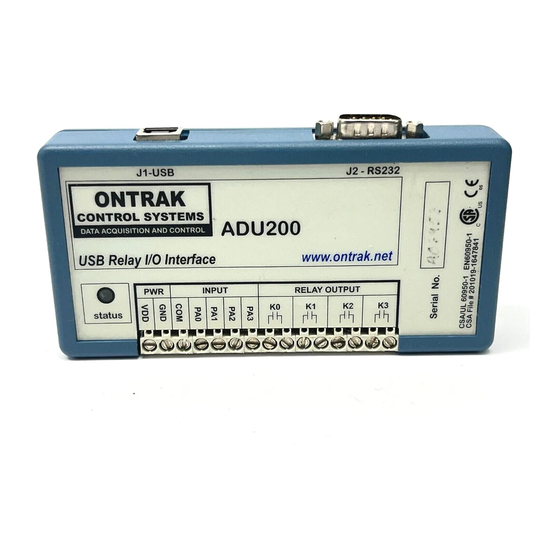
ADU200 Features The ADU200 STATUS LED AduHidTest USB Device Test Program ADU200 Command Summary ADU200 Command Descriptions 6a) Relay Commands 6b) Digital Input Commands 6c) Event Counter Commands 6d) Watchdog Timer Commands Specifications Dimensions Page 3 of 17 ADU200 User Manual... -
Page 4: What Is Included And Where To Start
.NET, Linux, Python, OSX etc.), and our AduHidtest software is available at: www.ontrak.net/programming.htm First time users should first review the ASCII command set for the ADU200 and then use AduHidTest USB test software to become familiar with the command syntax, and the operation of the various features of the product. -
Page 5: The Adu200 Status Led
-ADU200 disconnected from USB bus. The ADU200 can be connected to the USB bus via the enclosed 10' A-B USB cable. The cable provides both power and communications connections to the ADU200. When first connected, the STATUS led will turn RED indicating power is applied. -
Page 6: Aduhidtest Usb Device Test Program
AduHidTest is a Windows based USB device test program used to test the connection of ADU data acquisition devices to a USB port. The program is also a useful tool to allow programmers to become familiar with the ADU200 command set before programming in other languages. - Page 7 Figure 2: ShowList Window The window indicates that there is one ADU200 connected with serial number A02333. Select the device by double clicking on the text “ADU200 Serial Number = A02333”. The AduHidTest main window will now display the product ID and Serial number.
- Page 8 "SK0" (set relay K0) into the device pipe send window and click Send ADU. An OK will appear beside the Send ADU button if successful, as shown in Figure 4, and the ADU200 relay K0 will close. Note that ADU commands are not case sensitive.
- Page 9 Some commands cause a response to be sent from the ADU200 back to the host computer. For example, if an "RE3" (read event counter on PA3) command is sent, the ADU200 will send back the value of the event counter. To read responsive commands, simply click the Receive ADU button and the data will be displayed.
-
Page 10: Adu200 Command Summary
Sets de-bounce time of event counters (n=0, 1 or 2) (0 =10ms, 1 = 1ms, 2 = 100us) Returns present de-bounce setting. Watchdog Commands Sets watchdog timeout length. (n=0, 1, 2 or 3) (0=WD OFF, 1=1s, 2=10s, 3=1min) Returns watchdog setting. Page 10 of 17 ADU200 User Manual... -
Page 11: Adu200 Command Descriptions
ADU200 Command Descriptions 6a) Relay Commands (PORT K) The ADU200 interface feature four relay outputs. They are configured as PORT K with individual assignments of K0 thru K3. The relay contacts have no polarity requirements and switch either AC or DC loads. -
Page 12: 6B) Digital Input Commands
6b) Digital Input Commands (PORT A) The ADU200 interface contains one 4-bit input port PORTA, labelled PA0 to PA3. PORTA is isolated from all other external connections using opto-isolators with better than 2500V isolation. The COM connection is for connection of input device voltage common. - Page 13 Response (PA2 is High, PA0, PA1 and PA3 are Low) Returns status of PORT A in decimal format. Response is 2 bytes (00 to 15 in decimal) Response (All lines of PORTA are High) Page 13 of 17 ADU200 User Manual...
-
Page 14: 6C) Event Counter Commands
Returns present count and clears event counter (x = 0, 1, 2 or 3) Response 5 bytes (00000 to 65535 in decimal) 00156 Response (PA3 has seen 156 low to high transitions, event counter 3 is cleared) Page 14 of 17 ADU200 User Manual... -
Page 15: 6D) Watchdog Timer Commands
Response (De-bounce is currently set to 10ms) 6d) Watchdog Commands The ADU200 features a host watchdog function. The host watchdog, when enabled, resets all relays, and resets the watchdog setting to 0 (WD OFF), when a watchdog timeout occurs. Following the enabling of the watchdog timer, commands must be continuously received by the ADU200 within the selected timer interval or a watchdog timeout will occur. -
Page 16: Specifications
DC Ratings 5Amps@30VDC On-State Resistance Typical 30mOhm (Initial) Relay Used Panasonic APAN3105 Maximum Recommended 10 CPS Operating Speed CSA/UL EN60950-1 2 Edition Safety Approvals Mounting Options Desktop (STANDARD), Flange Mount, DIN Rail, Velcro Page 16 of 17 ADU200 User Manual... -
Page 17: Dimensions
Dimensions (Drawings not to scale) DESKTOP (STANDARD) FLANGE (OPTIONAL) (See www.ontrak.net for DIN RAIL options and dimensions.) Page 17 of 17 ADU200 User Manual...
Need help?
Do you have a question about the ADU200 and is the answer not in the manual?
Questions and answers