Table of Contents
Advertisement
Quick Links
MOTOR99 INSTRUCTION MANUAL
R E A D A L L I N S T R U C T I O N S A N D W A R N I N G S B E F O R E U S E
This manual provides important information on operation & maintenance. These instructions are not meant to cover every
possible condition and situation that may occur. We reserve the right to change this product at any time without prior notice.
F O R C O N S U M E R U S E O N L Y – N O T F O R P R O F E S S I O N A L U S E .
I F T H E R E I S A N Y Q U E S T I O N A B O U T A C O N D I T I O N B E I N G S A F E
O R U N S A F E , D O N O T O P E R A T E T H I S P R O D U C T !
DO NOT RETURN THIS PRODUCT TO THE RETAILER!
If you experience a problem, have questions or need parts for this product, call Customer Service at 1-888-287-6981,
M o n d a y - F r i d a y , 8 A M - 4 P M C e n t r a l T i m e . A copy of the sales receipt is required.
K E E P T H I S M A N U A L , S A L E S R E C E I P T & A P P L I C A B L E
W A R R A N T Y F O R F U T U R E R E F E R E N C E .
Keep this manual onboard in a waterproof bag when boating. The manual should stay with the outboard motor if sold.
2 YEAR LIMITED EMISSION-RELATED WARRANTY
THIS ENGINE MEETS U.S. EPA EMISSION STANDARDS UNDER 40 CFR 1054.625 .The emission-related limited warranty is
valid for two (2) years. Keep the purchase receipt and mail in the product registration card for proof of purchase. Buffalo Corp
limits emission-related warranty repairs to authorized service centers for owners located within 100 miles of an authorized
service center. For owners located more than 100 miles from an authorized service center, Buffalo Corp will, in its sole
discretion, either pay for shipping costs to and from an authorized service center, provide for a service technician to come to the
owner to make the warranty repair, or pay for the repair to be made at a local non-authorized service center. The provisions of
this paragraph apply only for the contiguous states, excluding the states with high-altitude areas identified in 40 CFR part 1068,
Appendix III.
To exercise this warranty, DO NOT RETURN TO RETAILER. Instead, call Customer Service toll free at 1-888-287-6981 (email
address info@buffalotools.com) and you will be instructed on where to take the engine for warranty service. Take the engine and
proof of purchase (your receipt) to the repair facility recommended by the Customer Service Representative. The warranty does
not extend to products damaged or affected by fuel contamination, accidents, neglect, misuse, unauthorized alterations, use in
an application for which the product was not designed and any other modifications or abuse.
1 YEAR LIMITED WARRANTY (30 Day Limited Warranty for Commercial and Rental Purpose)
Engines are warranted to be free from defects in materials and workmanship for a period of 1 YEAR from date of original
purchase. Buffalo Corp. is not liable for any indirect, incidental or consequential damages from the sale or use of this product.
Any implied warranties are limited to 1 YEAR as stated, or as otherwise stated, in this written limited warranty. Some states do
not allow the exclusion or limitation of incidental or consequential damages. Some states do not allow limitation on the length of
an implied warranty. Buffalo Corp will repair or replace, at its discretion, any part that is proven to be defective in materials or
workmanship under normal use during the 1 YEAR warranty period. Warranty repairs or replacements will be made without
charge for parts or labor. Parts replaced during warranty repairs will be considered as part of the original product and will have
the same warranty period as the original product. This warranty gives you specific legal rights, and you may have other rights
that vary state to state.
C A L I F O R N I A P R O P O S I T I O N 6 5
This product may contain chemicals, including lead, known to the State of California to cause cancer and
birth defects or other reproductive harm. Wash hands after handling.
Advertisement
Table of Contents

Related Manuals for Kuda MOTOR99

Summary of Contents for Kuda MOTOR99
- Page 1 MOTOR99 INSTRUCTION MANUAL R E A D A L L I N S T R U C T I O N S A N D W A R N I N G S B E F O R E U S E This manual provides important information on operation &...
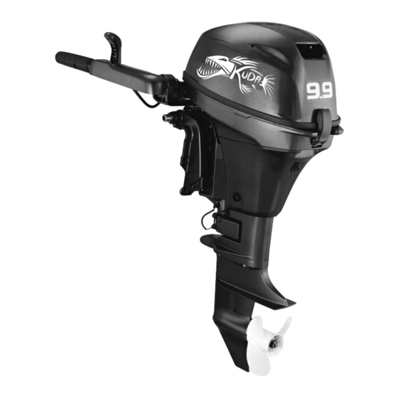
- Page 2 MOTOR99 9.9 HP OUTBOARD MOTOR SPECIFICATIONS: 4-Stroke Outboard Motor 9.9 HP @ 5000 RPM Adjustable Steering Friction Full Throttle RPM Range: 4500-5500 Displacement: 212 cc Engine type: 2 Cylinder Bore & Stroke: 2.2" x 1.7" Compression Ratio: 9.4:1 Fuel/Induction System: 1 OHV...
-
Page 3: Table Of Contents
TABLE OF CONTENTS Safety information......1 Propeller selection Outboard motor safety ....1 Start-in-gear protection Propeller ..........1 Engine oil requirements Rotating parts ........1 Fuel requirements Hot parts..........1 Gasoline 14 Electric shock Muddy or acidic water Power tilt. Anti-fouling paint 15 Engine shut-off cord (lanyard) Motor disposal requirements... - Page 4 Table of contents Instruments and indicators .... 27 Procedure Indicators........27 Trimming outboard motor 47 Low oil pressure-alert indicator ..27 Adjusting trim angle for manual tilt Engine control system....28 models 47 Alert system Adjusting trim angle (power tilt Low oil pressure alert models) 48 Installation...
- Page 5 Troubleshooting 77 Temporary action in emergency Impact damage Replacing fuse Power tilt will not operate 81 Starter will not operate Emergency starting engine 82 Engine fails to operate Emergency engine operation Treatment of submerged motor...
-
Page 6: Safety Information
Safety Information running away under power and leaving people Observe these precautions at all times. stranded, or running over people or objects. Propeller Always attach the engine shut-off cord to a People can be injured or killed if they come in secure place on your clothing or your arm or leg contact with the propeller. -
Page 7: Modifications
Safety Information Modifications and when operating above idle speed. Do not attempt to modify this outboard motor. Standing or sitting in non-designated locations Modifications to your outboard motor may reduce may result in being thrown either overboard or safety and reliability, and render the outboard within the boat due to waves, wakes, or sudden unsafe or illegal to use. -
Page 8: Weather
Safety Information Avoid sharp turns or other maneuvers that make it You may also want to consider an Internet- hard for others to avoid you or understand where you based program for basic boater education. The are going. Online Boating Safety Course provided by the Avoid areas with submerged objects or shallow Boat U.S. - Page 9 Safety information Contact the U.S. Coast Guard, the National Marine Retailers Association of America 155 N. Michigan Ave. Chicago, IL Association of State Boating Law Administrators, 60304 or your local Power Squadron for a complete set http://www.mraa.com/ of rules governing the waters in which you will be using your boat.
- Page 10 Safety Information You should slow down or change directions briefly and pass behind the other vessel. You should always move in such a way that the operator of the other vessel can see what you are doing. “The general prudential rule” This rule is called Rule 2 in the International Rules and says, “In obeying and construing these rules due regard...
- Page 11 Safety information Fishing vessel right-of-way All vessels that are fishing with nets, lines or trawls are considered to be “fishing vessels” under International Rules. Vessels with trolling lines are not considered fishing vessels. Fishing vessels have the right-of-way regardless of position.
- Page 12 Safety Information are white with black letters and orange boarders. Many bodies of water used by boaters are entirely within the boundaries of a particular state. The They signify speed zones, restricted areas, Uniform State Waterway Marking System has been danger areas, and general information.
- Page 13 Symbols Read Owner’s Manual The following symbols mean as follows. Notice/Warning Hazard caused by continuous rotation Electrical hazard...
-
Page 14: Specifications And Requirements
Specifications and Requirements Engine: Specifications TIP: Type: 4-stroke S “(AL)” stated in the specification data below Displacement: 139.0 cm³ represents the numerical value for the aluminum Bore ⋅stroke: propeller installed. 62.0 ⋅ 46.0 mm (2.44 ⋅ 1.81 in) Ignition system: CDI TIP: Spark plug (NGK): “*”... -
Page 15: Installation Requirements
Specifications and Requirements Recommended engine o i l : To lift and mount the outboard motor, 10W-30/ 10W-40/5W-30 people are necessary. API SE/SF/SG/SH/SJ/SL Propeller selection Next to selecting an outboard motor, selecting the Engine oil quantity: 27 ounces right propeller is one of the most important Lubrication: purchasing decisions a boater can make. - Page 16 ...
-
Page 17: Gasoline
Specifications and Requirements • As gasoline has changed, the amount of additives Avoid getting water and contaminants in such aromatics oxygenates the fuel tank. Contaminated fuel can cause increased. These additives are important for the poor performance or engine damage. Use engines in passenger cars, but they can have only fresh gasoline that has been stored in detrimental effects in marine engines, because of... - Page 18 ...
- Page 19 ...
- Page 20 Components...
- Page 21 ...
- Page 22 ...
- Page 23 Components Engine shut-off cord (lanyard) and clip The clip must be attached to the engine shut- off switch for the engine to run. The cord should be attached to a secure place on the operator’s clothing, or arm or leg. Should the operator fall overboard or leave the helm, the cord will pull out the clip, stopping ignition to the engine.
- Page 24 ...
-
Page 25: Manual Starter Handle
Components 1. Steering friction adjuster 1. Fuel joint cap To increase resistance, turn the steering Manual starter handle friction adjuster clockwise. Used to crank and start the engine. To decrease resistance, turn the steering friction adjuster counterclockwise. Trim rod (tilt pin) The trim rod (tilt pin) is used to adjust the trim angle of the outboard motor in relation to the angle of the boat transom. -
Page 26: Tilt Support Bar
Components Gear shift lever Tilt support bar Reverse position Tilted up position Shallow water cruising position Cowling lock lever Used to secure the top cowling 1. Tilt lock When the gear shift lever is moved to the neutral position forward position, outboard motor can be tilted up. -
Page 27: Installation
Installation The information presented in this section is in- tended as reference only. It is not possible to provide complete instructions for every possible boat and motor combination. Proper mounting depends in part on experience and the specific boat and motor combination. WARNING •... - Page 28 Installation Steering friction adjuster Mounting height Mount the outboard motor on the center line To run your boat at optimum efficiency, the (keel line) of the boat, and ensure that the boat water resistance (drag) of the boat and out- itself is well balanced.
-
Page 29: Clamping The Outboard Motor
Installation serious injury. Make sure the clamp screws NOTICE are tightened securely. Occasionally check the screws for tightness during operation. Check that the idle hole stays high enough to keep out water getting inside engine even if the boat is in stationary with maximum load. Incorrect engine height or obstructions to the smooth flow of water (such as the design or condition of the boat) can create airborne water... -
Page 30: Operation
Operation For the first hour of operation: First-time operation Run the engine at varying speeds up to 2000 r/min or approximately half throttle. Fill engine oil For the second hour of operation: The engine is shipped from the factory without engine 3000 r/min... -
Page 31: Fuel System
Operation Controls Removing top cowling Move the tiller handle fully to the left and right to For the following checks, remove the top check that operation is smooth. cowling from the bottom cowling. Turn the throttle grip from the fully closed To remove the top cowling, pull the cowling lock position to the fully open position. -
Page 32: Engine Shut-Off Cord (Lanyard)
Operation Oil filler cap Engine shut-off cord (lanyard) Oil lubrication check window Inspect the engine shut-off cord and clip for TIP: damage, such as cuts, breaks, and wear. lubrication check window does indicate the engine oil level. Use the oil lubrication check window to make sure that the engine is being lubricated with oil while it is running. -
Page 33: Engine
Operation Check to be sure the rubber seal is Engine seated correctly between the top cowling and the • Check the engine and engine mounting. bottom cowling. • Look for loose or damaged fasteners. Pull the cowling lock lever down to secure •... - Page 34 Operation WARNING Gasoline and its vapors are highly flammable and explosi Gasoline poisonous cause injury or death. Handle gasoline with care. Never siphon gasoline by mouth. If you should swallow some gasoline or inhale a lot of gasoline vapor, or get some gasoline in your eyes, see your doctor immediately.
-
Page 35: Operating Engine
Operation 6. Wipe up any spilled gasoline immediately with Fuel hose dry rags. Dispose of rags properly according to Fuel joint cap local laws or regulations. If you use a portable container to store and dispense fuel, only use a Remove the portable fuel tank from the locally approved GASOLINE container. - Page 36 Operation...
- Page 37 ...
- Page 38 ...
- Page 39 Operation boat could slow rapidly. This could cause people and objects in the boat to be thrown forward. Move the gear shift lever to the neutral position. Start mark “ ” Notch TIP: If the ambient temperature is -15°C or less, turn the throttle grip so that the engine start mark “...
- Page 40 ...
-
Page 41: Checks After Starting Engine
Operation TIP: Checks after starting engine It is not necessary to use the choke when Cooling water starting a warm engine, such as immediately Check for a steady flow of water from the cooling after the outboard motor has been operated water pilot hole. -
Page 42: Checks After Engine Warm Up
Operation After the engine has warmed up, push the choke NOTICE knob in fully. Failure to do so will shorten engine life. TIP: Before shifting the outboard motor, turn the If the choke knob is left pulled out after the throttle grip to the fully closed position and engine starts, the engine will stall. -
Page 43: Stopping Boat
Operation Stopping boat WARNING Do not use the reverse function to slow down or stop the boat as it could cause you to lose control, be ejected, or impact the load or other parts of the boat. This could increase the risk of serious injury. -
Page 44: Trimming Outboard Motor
Operation The trim angle of the outboard motor helps determine the position of the bow of the boat in the water. The correct trim angle is affected by variables, such as the load in the boat, sea conditions, and running speed. -
Page 45: Adjusting Boat Trim
Operation There are 5 holes provided in the clamp bracket to adjust the outboard motor trim angle. Stop the engine. Tilt the outboard motor up, and then remove the trim rod from the clamp bracket. Bow Up Too much trim-out puts the bow of the boat too high in the water. -
Page 46: Tilting Up And Down
Operation WARNI NG Leaking fuel is a fire hazard. When the outboard motor will be tilted up for more than a few minutes, tighten the air vent screw and fuel tank cap and align the fuel cock with the closed position. -
Page 47: Procedure For Tilting Down (Manual Tilt Models)
Operation Neutral position To prevent steering movement, turn the steering friction adjuster clockwise. Fuel hose Fuel joint cap Hold the rear of the top cowling and fully tilt the outboard motor up. Slightly lower the outboard motor from the fully tilted up position and fit the tilt support bar securely into the holder located on the clamp bracket. -
Page 48: Shallow Water
Operation When cruising in shallow water, do not operate i n reverse. Reverse thrust can cause the outboard motor to lift out of the water, increasing the chance of an accident and personal injury. 1. Tilt support bar NOTICE Turn the steering friction adjuster Do not tilt the outboard motor up so that the counterclockwise to set the steering friction... -
Page 49: Cruising In Other Conditions
Operation Hold the rear of the top cowling and slightly tilt the outboard motor up until the tilt support bar automatically locks. The outboard motor can be operated in this position for shallow water cruising. The outboard motor is equipped with 3 shallow water cruising positions. -
Page 50: Maintenance
Maintenance Tighten the fuel tank cap and air vent Transporting and storing outboard motor. screw securely. A WARNI NG • CARE when transporting a fuel container, whether in a boat or car. • DO NOT exceed the specified capacity of a fuel container. - Page 51 ...
- Page 52 ...
- Page 53 ...
-
Page 54: Procedure
Maintenance • Store the outboard motor in a dry, well- ventilated place, not in direct sunlight. Procedure Flushing in a test tank NOTICE Before starting the engine, make sure to supply water to the cooling water passages. Otherwise, the engine could overheat and Closed position be damaged. - Page 55 Maintenance Fill the test tank with fresh water to above Flushing with the water flush plug (optional) the level of the anti-cavitation plate. NOTICE: If the fresh water level is be- low the level of the NOTICE anti-cavitation plate, or if the water supply is Before starting the engine, make sure to insuffi- cient, engine seizure may occur.
-
Page 56: Lubrication
Maintenance TIP: For long-term storage, fogging the engine with oil is recommended. Cleaning and anticorrosion measures Wash down exterior outboard motor with fresh water and dry off completely. NOTICE: Do not spray water into the air intake. Spray the outboard motor exterior with "Silicone Protectant. -
Page 57: Periodic Maintenance
Maintenance Periodic maintenance WARNING Maintenance interval guidelines The service intervals provided in the Mainte- These procedures require mechanical skills, tools, and supplies. nance Chart were developed based upon "typical" use that includes operating at varied The procedures involve disassembling the motor and exposing dangerous parts. -
Page 58: Maintenance Chart
Maintenance Maintenance chart TIP: • Refer to the sections in this chapter for explanations of each owner-specific action. • The maintenance cycle on these charts assume usage of 100 hours per year and regular flushing of the cooling water passages. Maintenance frequency should be adjusted when operating the engine under adverse conditions such as extended trolling. - Page 59 M aintenance ...
- Page 60 ...
-
Page 61: Cleaning And Adjusting Spark Plug
Maintenance Be sure to use the specified spark plug, Cleaning and adjusting spark plug otherwise the engine may not operate properly. The spark plug is an important engine component. Before fitting the spark plug, measure the The condition of the spark plug can indicate electrode gap with a wire thickness gauge;... -
Page 62: Inspecting Idle Speed
Maintenance Start the engine. Warm it up and keep the idle speed for 5-10 minutes. Stop the engine and leave it for 5-10 Fuel filter minutes. Remove the top cowling. Inspecting idle speed Remove the oil filler cap. NOTICE When checking the engine idle speed, make sure to supply water to the cooling water passages by placing the outboard motor in the... - Page 63 Maintenance Install the oil filler cap and tighten it completely. 4-stroke outboard motor oil Engine oil quantity: 27 ounces Leave the outboard motor for 5-10 minutes. Remove the oil filler cap and wipe the Oil changer attached oil dipstick clean. Install the oil filler cap and tighten it If the oil changer is not available, remove completely.
-
Page 64: Checking Propeller
Maintenance Dispose of used oil according to local regulations. TIP: • Change the oil more often when operating the engine under adverse conditions such as extended trolling. Install the top cowling. Checking connector and lead • Check that each connector is connected securely. - Page 65 Maintenance NOTICE: reuse cotter pin installed. Otherwise the propeller can come off during operation. Cotter pin Propeller nut Washer Propeller TIP: Thrust washer If the propeller nut hole does not align with the Remove the propeller and thrust washer. propeller shaft hole...
- Page 66 ...
- Page 67 Maintenance Put a new gasket on the oil level plug. When the oil begins to flow out of the oil level plug hole, insert and tighten the oil level plug. Tightening torque: 9.0 Nm (0.92 kgf-m, 6.6 ft-lb) Put a new gasket on the gear oil drain screw.
- Page 68 Trouble Recovery Troubleshooting This section describes the likely causes and Q. Are engine inner parts damaged? remedies for problems, such as those in the A. Contact Customer Service. fuel, compression, and ignition systems, poor starting, and loss of power. Engine idles irregularly or stalls.
- Page 69 Trouble Recovery A. Loosen air vent screw. A. Remove foreign material and clean lower unit. 1. Is choke knob pulled out? Return to home position. 1. Is fuel system obstructed? A. Check for pinched or kinked fuel line or 1.
- Page 70 Trouble Recovery Connect correctly. Whether damage is found or not, return to the nearest harbor slowly and carefully. Inspect outboard motor before Engine vibrates excessively. operating it again. Is propeller damaged? Have propeller repaired or replaced. Starter will not operate If the starter mechanism does not operate (the Is propeller shaft damaged? engine cannot be cranked with the starter), the...
- Page 71 Trouble Recovery unguarded, rotating flywheel very dangerous. Keep loose clothing and other objects away when starting the engine. Use the emergency starter rope only as instructed. Do not touch the fly- wheel or other moving parts when the engine is running. Do not install the starter mechanism or top cowling after the engine is running.
- Page 72 Trouble Recovery Align the engine start mark “ ” on the throttle grip with the notch in the tiller handle. Insert the knotted end of the emergency starter rope into the notch in the flywheel magnet and Start mark “ ” wind the rope several turns around the flywheel Notch magnet clockwise.
- Page 73 PARTS LIST / PARTS DIAGRAM...
- Page 74 ...
- Page 75 ...
- Page 76 ...
- Page 77 ...
- Page 78 ...
- Page 79 ...
- Page 80 ...
- Page 81 ...
- Page 82 ...
- Page 83 ...
- Page 84 ...
- Page 85 ...
- Page 86 ...
- Page 87 ...
- Page 88 ...
- Page 89 ...
- Page 90 ...
- Page 91 ...
- Page 92 ...
- Page 93 ...
- Page 94 ...
- Page 95 ...
- Page 96 ...
- Page 97 ...
- Page 98 ...
Need help?
Do you have a question about the MOTOR99 and is the answer not in the manual?
Questions and answers