
Summary of Contents for Amer SD7FX1SC
- Page 1 Installation G G uide SD7FX1SC 10/100 Fast Ethernet Switch with 100FX Connectivity...
- Page 2 FCC NOTICE This device complies with Class B Part 15 the FCC Rules. Operation is subj e ct to the following two conditions: ( 1 ) This device may not cause harmful interference, and ( 2 ) this device must accept any interference received including the interference that may cause.
-
Page 3: Table Of Contents
Table of Contents 1. Introduction ................1 1.1 Features ................2 1.2 Specifications ................4 2. Installing the Switch .............5 2.1 Unpacking ................5 2.2 Checking AC Power ..............5 2.3 Installing the Switch ..............5 3.Making Network Connections .............6 3.1 Switched Ports ...............6 3.2 Making UTP Connections ............6 3.3 Making Fiber Connection ............8 4. -
Page 4: Introduction
1. Introduction This 8-port Fast Ethernet switch provides seven 10/100 RJ45 ports and one 100BASE-FX fiber port, each capable of transmitting or receiv- ing information simultaneously at full wire speed to control and allocate the network bandwidth. The key features of the switch series are: •... -
Page 5: Features
1.1 Features Designed for resolving congestion problems caused by bandwidth-hun- gry devices and bandwidth-intensive applications as well as a high num- ber of users, the switches not only adhere to the IEEE 802.3 10BASE-T, 802.3u 100BASE-TX and 100BASE-FX standards, but also feature: •... -
Page 6: Specifications
1.2 Specifications IEEE 802.3 10BASE-T, IEEE 802.3u 100BASE-TX std. 10/100 Ports Shielded RJ-45 jacks with Auto MDI-X detection Auto-negotiation capable Speed for 10Mbps or 100Mbps Full-duplex or half-duplex mode support IEEE 802.3u 100BASE-FX compliant 100FX Port Fixed 100Mbps operation Duplex mode selector - full duplex or half duplex IEEE 802.3x pause packet for full duplex operation Flow control Back-pressure for half duplex operation... - Page 7 100FX Port Fiber Specifications Model Ext Fiber Wavelength Tx Power Sens. Ref.Distance MMF 1310nm -19 ~ -14dBm -31dBm MMF 1310nm -19 ~ -14dBm -31dBm MT-RJ MMF 1310nm -19 ~ -14dBm -31dBm VF-45 MMF 1310nm -20 ~ -14dBm -31dBm -SA2 SMF 1310nm -15 ~ -8dBm -31dBm 20km -SL2...
-
Page 8: Installing The Switch
2. Installing the Switch 2.1 Unpacking Check to see that you have everything before you start the installation. • Installation guide • The switch unit • One AC power adapter for the unit 2.2 Checking AC Power Before you begin the installation, check the AC voltage of your area. The AC power adapter which is used to supply the DC power for the unit should have the AC voltage matching the commercial power voltage in your area. -
Page 9: Making Network Connections
3. Making Network Connections 3.1 Switched Ports The following figure shows the locations of the switched ports: 3.2 Making UTP Connections 10/100 TP Port Configuration All 10/100 TP ports support configuration as follows: Auto-negotiation capable Highest capability : 100M Full duplex Speed : auto-sensing for 100Mbps or 10Mbps Duplex : Full duplex, Half duplex Auto MDI-X function... -
Page 10: Making Fiber Connection
Cables Depending on the connection speed, use the proper UTP cables: Speed Cables used Distance 100M Cat. 5, 5e, or higher grade 100 meters Cat. 3, 4, 5, 5e, or higher grade 100 meters Auto-MDI-X Function An Auto-MDI-X function will automatically detect if a crossover is re- quired and make the swap of Tx pair and Rx pair internally. - Page 11 100FX Duplex Selector This selector is used for 100FX port duplex mode selection as follows: The following table lists the maximum MM fiber cable length connecting to different devices: Connected Device Distance (MMF cable) Network card half-duplex fiber port 400 m Network card full-duplex fiber port 2 km Class I hub half-duplex fiber port...
-
Page 12: Led Indicators
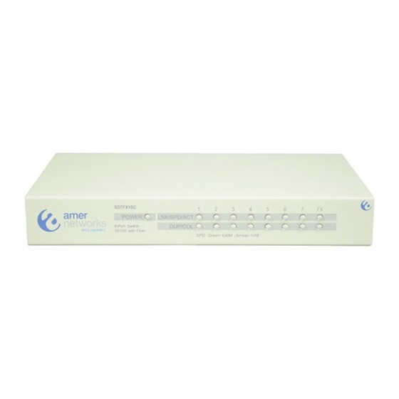
4. LED Indicators 4.1 LED Panel The switch provides comprehensive LED indicators for diagnosing and monitoring the operation of the switch as illustrated below: 4.2 Interpretation LED Functions POWER LED : indicates the power status of the switch. LNK/SPD/ACT LED : indicates the link status, connection speed status, and traffic status of the switched port DUP/COL LED : indicates the duplex status and collision status... - Page 13 Contact Information For technical support: support@amer.com For product information: info@ @ amer.com http://www.amer.com...
Need help?
Do you have a question about the SD7FX1SC and is the answer not in the manual?
Questions and answers