
Summary of Contents for Beeco WAUKESHA CHERRY-BURRELL UG Series
- Page 1 Read and understand this manual prior to installing, operating or maintaining this pump. WAUKESHA CHERRY-BURRELL SPECIFICATIONS UNIVERSAL UG SERIES INSTALLATION GEAR PUMPS & PARTS LIST...
- Page 2 95-03030...
-
Page 3: Safety
SAFETY Warnings, cautions and notes are contained in this manual. To avoid serious injury and/or possible damage to equipment, pay attention to these messages. WARNING Hazards or unsafe practices which COULD result in severe personal injury or death and how to avoid it. CAUTION Hazards or unsafe practices which COULD result in minor personal injury or product or property damage. -
Page 4: Table Of Contents
TABLE OF CONTENTS SAFETY ............3 RECEIVING AND WARRANTY ........5 Factory Inspection Receiving inspection Loss or Damage INTRODUCTION ............6 Specifications ............ 6 INSTALLATION ............7 Mounting Positions A, B, C, D ......7 BASIC DIMENSIONS 3UG..............8 6UG..............9 9UG.............. -
Page 5: Receiving And Warranty
RECEIVING AND WARRANTY Waukesha Cherry-Burrell Warranty Seller warrants its products to be free from defects in materials and workmanship for a period of one (1) year from the date of shipment. This warranty shall not apply to prod- ucts which require repair or replacement due to normal wear and tear or to products which are subjected to accident, misuse or improper maintenance. -
Page 6: Introduction
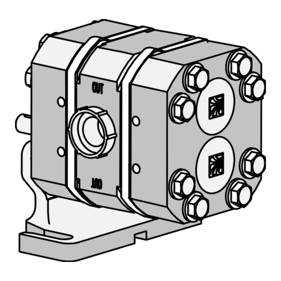
INTRODUCTION The Waukesha Cherry-Burrell UG Gear Pumps are external gear pumps designed for good metering accuracy and easy cleaning. Accuracy is provided by the high precision of the body, front and rear covers, and the gears. To enhance cleanability, mechanical seals are incorporated into both faces of the gears minimizing product in the pump and eliminating product from the drive keys and shaft area. -
Page 7: Installation
INSTALLATION MOUNTING There are four mounting positions that may be ordered. Position A contains has an upper drive shaft location and counterclockwise rotation (facing the liquid end of pump). To achieve any of the other 3 positions requires moving the mounting foot, switching shaft positions or both. -
Page 8: Basic Dimensions
INSTALLATION BASIC DIMENSIONS 95-03030... -
Page 9: 6Ug
INSTALLATION BASIC DIMENSIONS 95-03030... -
Page 10: 9Ug
INSTALLATION BASIC DIMENSIONS 95-03030... -
Page 11: Cutaway Drawing
INSTALLATION CUTAWAY DRAWING MOUNTING POSITION “D” SHOWN. SEE PAGE 7 FOR MOUNTING POSI- TIONS “A”, “ B”, AND “C” ITEM DESCRIPTION ITEM DESCRIPTION BODY IDLER SHAFT GEAR W/SEAL INSERTS KEY, DRIVE WEAR PLATE - FRONT RETAINING RING WEAR PLATE - REAR WASHERS COVER, FRONT BOLTS... -
Page 12: Bench Disassembly
SUGGESTED BENCH DISASSEMBLY (3UG SHOWN) (Pump is properly removed from system.) Remove four bolts and washers holding mounting foot on. Remove remaining four bolts/washers/nuts holding covers, wear plates, and body to- BOLTS AND gether. Remove two hollow spacers on WASHERS (4) Models 6 and 9 MOUNTING FOOT... - Page 13 SUGGESTED BENCH DISASSEMBLY (3UG SHOWN) RETAINING RING (4) NUTS BEARING (4) WASHERS ROLL PIN (4) REAR STATIONARY REAR COVER SEAL ASSEMBLY WEAR PLATE IDLER SHAFT SHAFT KEY (2) SHAFT O-RINGS (4) MOUNTING FOOT DRIVE BODY SHAFT FRONT FRONT COVER WEAR PLATE HOLLOW DOWEL...
-
Page 14: Complete Assembly
Complete Assembly Instructions - ALL UG FRONT OR REAR NOTE: Lubricate all O-rings and shafts with COVER silicone free lubricant. ROLL PINS BEARINGS RETAINER 1. Install Bearings, Retaining Rings, Roll Pins, RINGS and Bearing Caps. a. Press four new bearings into front and rear covers if required. - Page 15 Complete Assembly Instructions - (3UG shown) SEAL INSTALLATION NOTE: Lubricate all O-rings and shafts with USING #109921 SEAL silicone free lubricant. INSERTION PLUG AND #109922 SEAL 4. Install bolts and washers INSERTION SLEEVE a. Install four bolts with washers and hollow dowels *LAPPED 3 UG ONLY thru front cover.
- Page 16 Complete Assembly Instructions All UG 8. Install shafts a. Lubricate and install two shaft O-rings onto drive DRIVE shaft. SHAFT IDLER SHAFT b. Install key into drive shaft. SHAFT O-RINGS All lubricating must be done with approved silicone free lubricant. c.
- Page 17 Complete Assembly Instructions 3UGWP MOUNTING FOOT 10. Install Mounting Foot and remaining bolts a. Place mounting foot in position, and thread in the two bolts (with washers) already in place. b. Install the remaining two bolts and washers thru covers etc. and thread into mounting foot. c.
-
Page 18: Model 3Ug Gear Pump
MODEL UNIVERSAL 3UG PUMP ITEM PART NUMBER DESCRIPTION 108803 BODY 105819 GEAR W/SEAL INSERTS 109300 WEAR PLATE - FRONT 109301 WEAR PLATE - REAR 109423 COVER, FRONT 105812 STATIONARY SEAL 109424 COVER, REAR 105839 DOWEL, HOLLOW 30-124 ROLL PIN - E70020 STATIONARY SEAL O-RING EPDM V70020... -
Page 19: Model 6Ug Gear Pump
MODEL UNIVERSAL 6UG PUMP ITEM PART NUMBER DESCRIPTION 108804 BODY 107367 GEAR W/SEAL INSERTS 109301 WEAR PLATE - FRONT/ REAR 110924 COVER. FRONT/REAR 105812 STATIONARY SEAL 105839 DOWEL, HOLLOW 30-124 ROLL PIN E70020 STATIONARY SEAL O-RING EPDM V70020 STATIONARY SEAL O-RING VITON® K75020 STATIONARY SEAL O-RING KALREZ®... -
Page 20: Model 9Ug Gear Pump
MODEL UNIVERSAL 9UG PUMP ITEM PART NUMBER DESCRIPTION 108805 BODY 107368 GEAR W/SEAL INSERTS 109301 WEAR PLATE - FRONT/ REAR 109424 COVER. FRONT/REAR 105812 STATIONARY SEAL 110812 DOWEL, HOLLOW 30-124 ROLL PIN E70020 STATIONARY SEAL O-RING EPDM V70020 STATIONARY SEAL O-RING VITON® K75020 STATIONARY SEAL O-RING KALREZ®... -
Page 21: Parts Ordering Information
PARTS ORDERING EQUIPMENT INFORMATION Any correspondence concerning pump will require the following information be documented: PRODUCT NAME/MODEL___________________________________________________________ SERIAL NUMBER:_________________________________________________________ DATE OF PURCHASE:____________________________________ INVOICE NUMBER:_______________________________________ INVOICE DATE:__________________________________________ HOW TO ORDER PARTS By Phone Telephone your repair parts or fittings order to your Distributor. To speed your order and avoid delays, please have your equipment model and serial number and the part numbers from the parts list before you call your Distributor. - Page 22 Have a problem with this Manual? Our mission is to provide you with a quality Manual to match our quality products. If you feel the instructions for the installation and maintenance of this product are lacking or incorrect in any manner, please tell us. Your efforts to assist us will be greatly appreciated.
- Page 23 95-03030...
- Page 24 611 SUGAR CREEK ROAD DELAVAN, Wl 53115 U.S.A. CUSTOMER SERVICE TELEPHONE 1-800-252-5200 or 262-728-1900 TOLL FREE TELEFAX 1-800-252-5012 or 262-728-4904 95-03030 Effective Date: October 19, 1998...