Table of Contents
Advertisement
Quick Links
Advertisement
Table of Contents

Summary of Contents for Legend 780
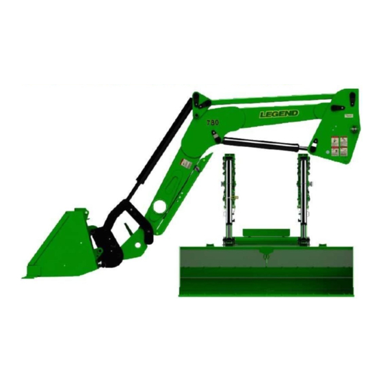
- Page 1 OWNERS MANUAL 11/18/21 MANUAL NO. 698249 780 LOADER Self-Leveling & Non Self-Leveling IMPORTANT-KOYKER DEALER BE SURE THIS MANUAL IS GIVEN TO THE PURCHASER FOR FUTURE REFERENCE KOYKER MANUFACTURING CO., P.O. BOX 409 LENNOX, SD 57039 Phone 1-800-456-1107 E-mail koyker@koykermfg.com...
-
Page 2: Table Of Contents
SERVICE AND MAINTENANCE 780 SL & NSL Specifications ......................13-14 Loader Inspection, Service, and Maintenance ..................15 780 SL Hydraulic System Parts List ..................... 16 780 SL Hydraulic System Parts Diagram ..................... 17 780 NSL Hydraulic System Parts List ....................18 780 NSL Hydraulic System Parts Diagram .................. -
Page 3: Introduction
INTRODUCTION Koyker Manufacturing Inc. has engineered and manufactured a Legend Loader that includes the features YOU want in a top-of-the-line loader, including: -Greaseless Pivot Connections -Large Chrome Pivot Pins -Bucket Linkage for Increased Roll Back Angle and Force -Euro Attachment System... -
Page 4: Safety Alert Symbol
SAFETY ALERT SYMBOL The symbol shown below is used to call your attention to instructions concerning your personal safety. Watch for this symbol it points out important safety precautions. It means ATTENTION! Become Alert! Your Personal Safety Is Involved! Read the message that follows and be alert to the possibility of personal injury or death. DANGER: Indicates an imminently hazardous situation that, if not avoided, will result in death or serious injury. -
Page 5: Safety Information
SAFETY Improper use of a loader can cause serious injury or death. The following safety precautions, and those given on the tractor mount installation instructions, should be thoroughly understood before attempting to operate this machine. BEFORE OPERATING: Carefully study and understand this manual, the specific tractor mount instructions, and the attachment(s) manual(s). - Page 6 SAFETY CONTINUED Transport the machine load at the slowest speed possible and with the loader boom at the lowest transport position to avoid tipping or upsetting, which may result in serious injury or death. Be extremely careful when working on inclines or near loose fill, rocks, and holes as they can cause tipping or upsetting which may result in serious injury or death.
- Page 7 SAFETY CONTINUED PERFORMING MAINTENANCE: Carefully review, understand, and follow the “maintenance” section in this owners manual before attempting to service loader. Lower the bucket or attachment to the ground, shut off tractor engine, and relieve pressure in the hydraulic system before adjusting, or servicing the loader. Escaping hydraulic oil under pressure can penetrate the skin.
-
Page 8: Safety Decals
SAFETY DECALS Page 6... -
Page 9: Tractor & Safety Pointers
TRACTOR & SAFETY POINTERS The use of good judgment and common sense is necessary by the operator in using this loader. The front and rear wheels should be set for the widest wheel tread to assure best stability. Use extra caution when rear wheel weights and tire ballast are added to a loader-equipped tractor. -
Page 10: Attaching Loader
ATTACHING LOADER IMPORTANT: Never attempt loader attachment on grades which are not reasonably level. 1. Check to be sure that the surfaces of the mounts are free of obstructions. (Fig 8-1) 2. Drive the tractor slowly and carefully in between the loader arms only far enough to permit hook-up of the hydraulic system hoses. -
Page 11: Attaching Bucket
ATTACHING BUCKET Prior to attaching the bucket, prepare the adapter for engagement by pulling the adapter handle back (towards the operator) into it’s cocked position. With the bucket positioned on level ground, tilt the bucket adapter forward approximately 45º. (Fig 9-1) Slowly drive forward into the bucket, centering the adapter with the bucket as you go and position the top mount bar of the adapter just below the hooks on the back side of the bucket. -
Page 12: Detaching Loader
DETACHING LOADER IMPORTANT: Never attempt loader attachment on grades which are not reasonably level. Raise loader frame slightly to permit loader stand reengagement. (Fig. 10-1) Lower bucket to ground and tip slightly forward to apply pressure to mount connection. Note: This will prevent the loader from inadvertently rocking forward when the mount pins are removed and uprights are disengaged from it’s cradle. -
Page 13: Detaching Bucket
DETACHING BUCKET Prior to detaching the bucket, prepare the adapter for disengagement by pulling the adapter han- dle back (towards the operator) into its cocked position (Fig 11-1 & Fig 11-2). The bucket should be resting on level ground. Slowly lower and dump your way out of the bucket (Fig 11-3). Slowly back away from the bucket until you are clear of the bucket and safe to maneuver (Fig 11-4). - Page 14 OPERATION WARNING: Never allow anyone to operate the loader until they have carefully reviewed and understood this owners manual. FILLING THE BUCKET: When manure is piled on a slope, it is best to drive tractor up the slope straight into the pile. Operating sideways on a slope has a tendency to tip the loading unit.
-
Page 15: Operational
SPECIFICATIONS KOYKER LEGEND 780 SL LOADER SPECIFICATIONS Description of Equipment Rated Loader Model ........................780 SL Attachment Adapter & Bucket Size ..................6’ Rated Flow ........................25 GPM Maximum Pressure ......................2500 PSI Lift Cylinder Dia......................3 1/4” Bore Attachment Cylinder Dia. - Page 16 SPECIFICATIONS KOYKER LEGEND 780 NSL LOADER SPECIFICATIONS Description of Equipment Rated Loader Model ......................... 780 NSL Attachment Adapter & Bucket Size ................6’ Bucket Rated Flow ........................25 GPM Maximum Pressure ......................2500 PSI Lift Cylinder Dia......................3 1/4” Bore Attachment Cylinder Dia.
-
Page 17: Loader Inspection, Service, And Maintenance
LOADER INSPECTION, SERVICE, AND MAINTENANCE Lower the bucket to the ground, shut off tractor engine, and relieve the pressure in the hydraulic system before adjusting, lubricating, or servicing the loader. Periodically check all bolts for looseness and re-torque if necessary. Before storage, be certain all hydraulic cylinders are fully collapsed so that the rod will not be exposed to the elements or damaged. -
Page 18: 780 Sl Hydraulic System Parts List
780 SL HYDRAULIC SYSTEM PARTS LIST ITEM NO. PART NO. DESCRIPTION QTY. 679260 3 1/4" LIFT CYLINDER 680735 3 1/4' BUCKET CYLINDER 679760A 1ST OIL LINE (A) 679761A 2ND OIL LINE (A) 679762A 3RD OIL LINE (A) 679763A 4TH OIL LINE (A) -
Page 19: 780 Sl Hydraulic System Parts Diagram
780 SL HYDRAULIC SYSTEM PARTS DIAGRAM Page 17... -
Page 20: 780 Nsl Hydraulic System Parts List
780 NSL HYDRAULIC SYSTEM PARTS LIST ITEM NO. PART NO. DESCRIPTION QTY. 679260 3 1/4" LIFT CYLINDER 680735 3 1/4' BUCKET CYLINDER 679444 1ST OIL LINE 679445 2ND OIL LINE 679446 3RD OIL LINE 679447 4TH OIL LINE 670417 30" HYDRAULIC HOSE 663188 18"... -
Page 21: 780 Nsl Hydraulic System Parts Diagram
780 NSL HYDRAULIC SYSTEM PARTS DIAGRAM Page 19... -
Page 22: 780 Nsl Loader Parts Diagram
KOYKER “LEGEND 780 NSL” LOADER PARTS DIAGRAM Page 20... -
Page 23: 780 Nsl Parts Identification Schedule
PARTS IDENTIFICATION SCHEDULE ITEM NO. PART NO. DESCRIPTION QTY. 694711 RH UPRIGHT WLDT- 780 NSL 694712 LH UPRIGHT WLDT– 780 NSL 679453 MAIN FRAME WLDT 675076 OIL LINE COVER PLATE 679260 LIFT CYLINDER ASSEMBLY 680735 BUCKET CYLINDER ASSEMBLY 679258 LH REAR LINKAGE WLDT... - Page 24 PARTS IDENTIFICATION CONTINUED ITEM NO. PART NO. DESCRIPTION QTY. 676798 INSERT .313-18 673615 SCREW - .3125-18 X 2.0 GR 5 HHSLDR 640246 #6 HITCH PIN 640671 HITCH PN #3 681165 CLEVIS PIN 3/4” DIA X 2” 683298 SCREW - .4375-14 X 5.00 GR 5 HHC 640050 SCREW - .4375-14 X 1.5 FHHC 640049...
-
Page 25: 780 Sl Loader Parts Diagram
KOYKER “LEGEND 780 SL” LOADER PARTS DIAGRAM Page 23... -
Page 26: 780 Sl Parts Identification Schedule
PARTS IDENTIFICATION SCHEDULE ITEM NO. PART NO. DESCRIPTION QTY. 694740 RH UPRIGHT WLDT - 780 SL 694741 LH UPRIGHT WLDT - 780 SL 678254 MAIN FRAME WLDT 679260 LIFT CYLINDER ASSEMBLY 679246 BUCKET CYLINDER ASSEMBLY 679238 EURO ATTACHMENT ASSEMBLY 679257... - Page 27 PARTS IDENTIFICATION CONTINUED ITEM NO. PART NO. DESCRIPTION QTY. 673615 SCREW - .3125-18 X 2.0 GR 5 HHSLDR 687854 INSERT - .313-18 676798 INSERT - .313-18 640246 #6 HITCH PIN 640671 HITCH PIN #3 676797 SCREW - .3125-18 X2.50 HHSLDR 683298 SCREW - .4375-14 X 5.00 GR 5 HHC 640050...
-
Page 28: Euro Adapter Parts Diagram
EURO/GLOBAL ADAPTER PARTS DIAGRAM Page 26... -
Page 29: Euro Adapter Parts Identification Schedule
EURO ADAPTER PARTS IDENTIFICATION SCHEDULE ITEM NO. PART NO. DESCRIPTION QTY. 680769 Euro Adapter Handle (Painted) 679304 .79" (20 MM) x 8" Pivot Pin 679308 EXTENSION SPRING 680766 CROSS MEMBER WLDT 679316 EURO ATTACHMENT WLDT 657632 ZERK-1/4-28 GREASE 640032 SCREW-.375-16 X 1.25 GR 5 HHC 680761 CLEVIS PIN .5"... -
Page 30: Bucket Parts Diagram
BUCKET PARTS DIAGRAM Page 28... -
Page 31: Bucket Parts Identification Schedule
BUCKET PARTS IDENTIFICATION SCHEDULE Optional Euro Buckets with Bolt-on Blade & Clevis 7’ Euro Bucket ITEM NO. PART NO. DESCRIPTION QTY. 689073 7' EURO BUCKET WELDMENT 672847 7' BOLT ON BUCKET BLADE (PAINTED) 672852 BUCKET CLEVIS 673286 SLING LINK 673366 SCREW - .625-11 X 2.00 GR 5 PH 640159 WASHER - 5/8"... -
Page 32: Multi-Faster & Accumulator Kit Parts Diagram
MULTI-FASTER & ACCUMULATOR KIT PARTS DIAGRAM SOFT RIDE FEATURE The soft ride feature was designed to diminish the stresses on the tractor, mounts, loader and operator while transporting heavy loads to and from the field. The soft ride feature incorporates a pre-charged nitrogen accumulator to act as a shock absorber similar to that of an automobile. -
Page 33: Multi-Faster & Accumulator Kit Parts Identification Schedule
MULTI-FASTER & ACCUMULATOR KIT PARTS SCHEDULE ITEM NO. PART NO. DESCRIPTION QTY. 695751 MULTIFSASTER 679727 ACCUMULATOR BRACKET 679791 ACCUMULATOR BLOCK 679726 SOFT RIDE ACCUMULATOR 680744 1/2” BALL VALVE 641429 FITTING - HYD 45 ELB 8MJX-8ORM 681471 FITTING - HYD TEE 8MJX-8FJX-8MJX 679796 FITTING - HYD 8ORM-8ORM 674672... -
Page 34: Hydraulic Cylinder Information
CYLINDERS IMPORTANT: Read these service tips before beginning assembly of cylinder gland or piston. 1. Keep seals clean from the time they are removed from package until they are installed. 2. Clean the groove or bore into which the seal is to be fitted before installing the seal. 3. -
Page 35: Hydraulics Information
HYDRAULIC SYSTEM The hoses from the tractor valves are attached to the oil lines which are on the inside of the loader main frame. Re-check all joints to prevent leakage after loader is mounted and in operation. KEEP SYSTEM CLEAN - USE ONLY CLEAN OIL CAUTION! It is of utmost importance that the hydraulic system of this loader be kept free from dirt and foreign matter. -
Page 36: 1/4" Cylinder Service Kit
3 1/4” CYLINDER SERVICE KITS WITH 1 3/4” SHAFT KIT NO. 675574: COMPLETE KIT WITH ALL SEALS NEEDED TO SERVICE ONE (1) 3 1/4" CYLINDER CONSISTS OF: 1 EACH 3 1/4" GLAND "O" RING 1 EACH 3 1/4" BACKUP RING 1 EACH 1 3/4"... -
Page 37: Hydraulic Cylinder Parts List
HYDRAULIC CYLINDER PARTS LIST LIFT CYLINDER (Part No. 679260—780SL & 780NSL) ITEM NO. PART NO. DESCRIPTION QTY. 679261 TUBE WELDMENT 661017 NUT - 1.00-14 GR C LOCK THIN 675577 PISTON ASSEMBLY 640301 1" O-RING 675570 GLAND ASSEMBLY 679262 ROD WELDMENT BUCKET CYLINDER (Part No. -
Page 38: Hydraulic Cylinder Parts Diagram
HYDRAULIC CYLINDER PARTS DIAGRAM Page 36... -
Page 39: Piston And Gland Diagram
CYLINDER GLAND SERVICE DIAGRAM Note: To install rod wiper and U-cup seal, fold All gland seals shown with a section similar to shape shown below, slip into gland removed to facilitate correct installation. bore and locate each in its respective groove. ROD WIPER Tools are used to fold seals, take care not to damage sealing surfaces. -
Page 40: Limited Warranty
C. ITEMS COVERED SEPARATELY. The Legend warranties do not cover any parts, components or materials that are part of the Product, or used in conjunction with the Product, that are not manufactured by Legend. Such parts, components and materials will be subject to the warranties provided by the manufacturer, if any. -
Page 41: Torque Specifications Torque Specifications
TORQUE SPECIFICATIONS 1. Tightening Bolts & Nuts Check all loader bolts and nuts for tightness every 50 working hours. The movement of the loader over rough terrain may cause bolts to come under pressure and over a long period of time some slight stretching of the bolt may occur.
Need help?
Do you have a question about the 780 and is the answer not in the manual?
Questions and answers