Table of Contents
Advertisement
Quick Links
Advertisement
Table of Contents

Summary of Contents for infiniDome GPSdome 1.01
- Page 1 GPSdome Rev 1.01/1.01-DF Installation Manual...
- Page 2 Contents nIrtnudortnI ..................................3 wrvtrtvO ..................................3 sndrtnIC ................................... 4 nICrnllnrtnI ..................................4 nICrnllnrtnItstr .................................. 4 ceRtSvovtrvttReCrvPtOtritceRunPv ........................5 RrotsnnlvCtsnIIvorntC ............................... 5 nICrnllnrtnItetnovudtv ..............................6 cvIvtnltw vtnrtnI ................................8 rntIrvInIov ..................................8 gtndnlvCinnrtIT ................................9 tvl tnIutRd ntr ................................9 R votatonrtnIC ................................
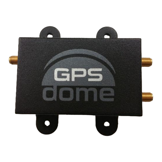
- Page 3 GPSdome may be used in a range of applications. This manual is written for both GPSdome 1.01 and GPSdome 1.01-DF Overview GPSdome (see Figures 1a, 1b and 2) is a compact, light-weight GPS anti-jamming module, designed to prevent loss of position fix and time in the presence of certain types of jammers.
-
Page 4: Installation
(4) During installation, ensure there is NO power applied to the module OR the GPS receiver. (5) When making power connections to the GPSdome 1.01-DF, verify correct polarity. Connecting power with reverse polarity will damage the unit and void warranty. - Page 5 GPS Receiver DC feed 2.75VDC (Existing) & GPS Signal Active GPS RF signal at 1575MHz to receiver Antenna Figure 3a: GPS Receiver with GPSdome 1.01 Integrated Active GPS RF signal at Antenna 1575MHz to receiver GPSdome GPS Receiver DC feed 2.75VDC (Existing) &...
- Page 6 Installation Procedure Before commencing the installation procedure read the CAUTIONS detailed on page 4. The following instructions are provided to install the GPSdome system: NOTES: (1) Installation and methods used to secure the GPSdome system may vary depending on the application.
- Page 7 Microwave LMR-100A-PVC fitted with high quality sealed SMA connectors. The other end connected into the GPS receiver RF antenna input. Step 5. Prepare for powering up. For GPSdome 1.01, verify that the DC provided on the receiver cable is 3-12VDC and can provide at least 700mW of power.
-
Page 8: General Operation
For GPSdome 1.01-DF, connect the red and black wires to a power source of 3-32VDC, red wire to +V and the black to common (GND). If Jamming indication is required, use the white or brown wire (and the same common – black), in accordance with attachment A. -
Page 9: Troubleshooting
Check that the GPSdome ‘R’ connector is connected to the GPS receiver, and that the SMA connectors are tightened at both ends. Check that 3-12V power is connected to GPSdome 1.01 from the receiver and the receiver is capable of providing the required current or, for GPSdome 1.01-DF, the red and black wires are connected properly to an applicable power source (red to + 3-32VDC and black to common/GND). -
Page 10: Specifications
Specifications Table 2 details the Environmental & Electrical Specifications. All specifications are at nominal supply (3 - 12V) and temperature (+25°C) unless otherwise stated. Table 2: Environmental & Electrical Specifications Item Parameter Description/notes Value Units Min. Typ. Physical Operational Environmental Temperature ˚C range... - Page 11 Attachment A – Integrating the Jamming Indication The custom integrated circuit at the core of GPSdome has a diagnostic logic output to indicate the presence of jamming energy. It provides a ‘basic indication’ of an active jammer being present or not. Its switch point is a function of external antenna LNA gain and so cannot be precisely specified.
Need help?
Do you have a question about the GPSdome 1.01 and is the answer not in the manual?
Questions and answers