Table of Contents

Summary of Contents for Soil Instruments Digital Inclinometer Pro
- Page 1 Digital Inclinometer Pro User Manual Soil Instruments Limited has an ongoing policy of design review and reserves the right to amend these specifications without notice. Man251 - Digital Inclinometer Pro – MN1114 – Rev1.2.5...
- Page 2 What’s this manual about? This manual tells you about the Digital Inclinometer Pro and how to use it to take readings of lateral deflections. Who does this apply to? Installers, field engineers and technicians using the Digital Inclinometer Pro. QUESTION...
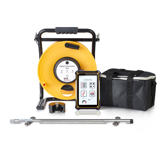
- Page 3 Digital Inclinometer Pro. Digital Inclinometer Pro. The Digital Inclinometer Pro comprises a biaxial probe, cable reel and a rugged Tablet supplied with ‘In-Port Pro’ application. The inclinometer probe measures lateral deflections using...
-
Page 4: Table Of Contents
Front Panel LED’s Power Button & Power LED Comms Ready/Bluetooth LED Battery LED QUICK START GUIDE Using The Digital Inclinometer Pro Before You Go To Site Charging The Battery Detachable inclinometer Pro Connection In-Port Pro App Overview In-Port Pro Software... - Page 5 Technical Details Reading Units Files and Folders File Management MAINTENANCE GUIDE Maintaining the Digital Inclinometer Pro System Routine Maintenance Cable Maintenance Probe Inspection and Maintenance Cable Inspection and Maintenance APPENDICES Appendix A - Data Download Format and Manual Data Reduction...
-
Page 6: Overview & Introduction
Tips give additional information that may be helpful when using the Digital Inclinometer Pro. PRODUCT Soil Instruments has an on-going policy of design review and reserves CHANGES the right to amend the design of their product and this instruction manual without notice. -
Page 7: About Inclinometers
System Description Things You Need to Know About the Digital Inclinometer Pro ABOUT An inclinometer system includes inclinometer casing, a traversing INCLINOMETERS probe, control cable, and tablet. Inclinometer casing is permanently installed in a near-vertical borehole that passes through a zone of suspected movement. The probe, cable, and tablet are used to survey the casing. -
Page 8: The Digital Inclinometer Pro
THE DIGITAL The Digital Inclinmeter Pro is supplied in metric and English versions. INCLINOMETER The metric version has a gauge length of 0.5m. The English version has a gauge length of 2 feet. A + mark is engraved on the body of the probe. This is used to orient the probe during a survey. - Page 9 If you are using your Digital Inclinometer Pro system in new boreholes then the following does not apply. However if you use a Digital Inclinometer Pro in a Borehole that has previously been read using a mid-probe datum inclinometer you will see anomalies in the data plots when comparing the previous borehole runs with the new borehole runs.
-
Page 10: Control Cable
Option 3 • Use the Depth Index adjustment feature in In-Profile to reposition the previous data sets. • See article Using In-Profile Depth Index Correction. HANDLING THE The inclinometer probe is a sensitive measuring intrument. handle it PROBE with care. •... -
Page 11: Front Panel Led's
QUICK START GUIDE Using the Digital Inclinometer Pro • BEFORE YOU GO Unpack the Digital Inclinometer Pro, retaining the packaging for TO SITE future carriage to Soil Instruments for calibration. • Charge the Digital Inclinometer Pro by carefully following the charging procedure below;... -
Page 12: Charging The Battery
The adaptor provides 12 Vdc. Polarity of barrel connector is +ve inside and -ve outside. Follow the charging procedure outlined in this manual at all times to properly maintain the Digital Inclinometer Pro System. Only use the charger supplied, using other chargers will invalidate the warrenty. - Page 13 2. Pair together the 2 caps and place in a safe secure location 3. Check for any contaminants on the connectors and on the probes O-ring, removing any contaminants with a damp cloth is necessary. 4. Line up the largest keyways on the connectors and push together. 5.
- Page 14 6. The probe is now connected. DISASSEMBLY 1. After use, wipe off any moisture around the connection. 2. Use the 22mm spanner and unfasten the Collar Nut. 3. Pull the Connection apart 4. Check that the O-ring is clean and wipe down the connectors. 5.
-
Page 15: In-Port Pro App Overview
Please retain the packaging supplied with the Vertical Digital Inclinometer System to ensure safe carriage when returning to Soil Instruments for future calibration. Soil Instruments will reduce calibration costs if the system is returned in its original packaging. IMPORTANT INFORMATION... -
Page 16: Action Bar
ACTION BAR The ‘Action Bar’ contains tap icons that vary depending on the screen. Add (Inclinometer) Done Cancel Pause (Survey) Adding An Inclinometer The App keeps a list of inclinometers along with INCLINOMETER the survey data for each inclinometer. To see the LIST list, tap the Survey icon (See right). -
Page 17: Fields On The Inclinometer Form
4. Tap “Done” when the form is complete. Done FIELDS ON THE Site & Inclinometer: These two fields are used together to identify an INCLINOMETER inclinometer. Each field can contain 12 characters. FORM Description: Optional. (35 Max Characters) A0 direction: Optional. Compass heading 0 to 359. North = 0, South = 180 Units: Tap to switch between metric and English units. -
Page 18: Recording Inclinometer Surveys
You must not cut the casing if readings have been taken previously. IMPORTANT INFORMATION Soil Instruments recommend marking the A0 direction on the inclinometer casing with a permanent marker to make sure the borehole is always read with the correct orientation. -
Page 19: Orientation Of Probes
ORIENTATION OF 0-Pass Readings: For the 0 pass, insert the probe with the + mark PROBE facing the A0 direction. The + mark appears on the body of the probe above the top wheel set. 180-Pass Readings: For the 180 pass, remove the probe, rotate it 180°, and insert it with the + mark facing the A180 groove. -
Page 20: The Survey Screen
THE SURVEY The survey screen guides you through the survey. SCREEN 0-PASS SCREEN The elements of the survey screen are explained below. Inclinometer Name Pass Active Depth Last Recorded Depth A Reading Units B Reading Progress Bar Record Button 180-PASS SCREEN The 180-Pass screen adds checksums and a second progress bar. -
Page 21: Survey Buttons
SURVEY BUTTONS The record button is yellow when readings are not stable. The record button is green when readings are stable and ready to record. If the button stays yellow or flickers between green and yellow, tap to record the reading anyway. Wait for stable readings Readings are stable. -
Page 22: Halting Asurvey
HALTING A 1. Tap Pause to halt the survey for any reason. SURVEY Pause (Survey) 2. Make a choice, then tap OK. Or tap Cancel to resume the survey. Abandon: Deletes the current survey. Bookmark: Sets a bookmark at the last recorded reading. Done: Saves the current survey as is. -
Page 23: Recording The Survey
RECORDING THE 1. Switch on Reel and Reader. Tap the In-Port Pro icon SURVEY to start the app. Wait for a steady blue glow from the Bluetooth LED to show that a connection has been made. 2. Tap “Survey” 3. Tap the inclinometer to survey. - Page 24 4. The reader displays the start depth for the survey. Insert the probe, with + mark facing the A0 groove, and lower it to the start depth. Do not allow the inclinometer probe to drop to the bottom of the borehole of its own accord as this will result in damage to the inclinometer probe components and calibration.
-
Page 25: Recording The 0-Pass
RECORDING THE 1. Switch on In-Port Pro and tap “Start 0 Pass” 0-PASS 2. The A and B readings appear. The probe has been immobile, so readings are stable. Tap to record. - Page 26 3. The tablet displays the next active depth. Raise the probe to this depth and wait for stable readings. The last recorded depth appears just below the new active depth. 4. Tap the record button when it is green. 5. The tablet displays the next active depth. Raise the probe to this depth, wait for stable readings, and then tap the record button.
- Page 27 Now the tablet displays the top depth. Raise the probe to this depth and wait for a stable reading. 7. Tap when the record button is green.
- Page 28 8. Tap “End 0 Pass”. This disables recording so you can handle the probe. 9. Now the tablet displays the start depth for the 180-Pass. Recording is still disabled. Remove the probe, rotate it 180 degrees, and insert it with the + mark facing the A180 groove.
-
Page 29: Recording The 180-Pass
RECORDING THE 1. Tap “Start 180 Pass”. This enables recording. 180 PASS 2. Tap the record button when it is green. You can see checksums now. - Page 30 3. The tablet displays the next active depth. Raise the probe to this depth and wait for a stable reading. 4. Tap the record button when it is green. 5. The tablet displays the next active depth. Raise the Probe to this depth, wait for stable readings, and then tap the record button.
- Page 31 6. Now the tablet displays the top depth. Wait for a stable reading. 7. Tap the record button when it is green.
- Page 32 6. Tap “End 180 Pass”. The survey is complete. The app saved readings during the survey so there is no need to save anything now. When you tap the “End” button, the app takes you to the “Plot” screen.
-
Page 33: Detailed Software Guide
DETAILED SOFTWARE GUIDE Plotting Inclinometer Surveys INTRODUCTION The In-Port Pro app can display four types of plots. These are useful for validating the survey. These plots cannot be printed directly, but if necessary, you can take screen shots, transfer them to a PC, and print them using Word. -
Page 34: Advanced Borehole Features
Advanced Borehole Features AUTORUN As well as manually recording the readings the system can (HANDS-FREE automatically record readings with nothing more than a pull on the MODE) cable. You can switch between the two methods of readings whenever you like, even if you are already partway through a run. Press the ‘Menu’... -
Page 35: Qr Code Feature
When performing the run this way, the prompt buttons at the bottom of the screen will change in the following way. “Pull” will appear to inform you to pull the cable up to the next depth marker, this will initiate the saving process. “Save”... -
Page 36: Sending Data Files To A Pc
Sending Data Files to a PC There are three ways to transfer inclinometer files (.dux files) from the Reader to a PC. 1. USB (Completely manual, requires USB connection cable). 2. Email (Partially automated, requires internet access). 3. Dropbox (More automated, requires internet access). USB TRANSFERS This method requires the USB cable supplied with your Reader device and the Windows file manager (Windows Explorer). - Page 37 3. Click on the In-Port Pro folder. 4. Click on the “Outbox” folder. This folder holds any updated inclinometer files. 5. Copy all the .dux files in the Outbox and paste them into a folder on your PC. 6. (Optional) Verify that the .dux files are on your PC, then delete the files in the Outbox.
-
Page 38: Email Transfers
EMAIL TRANSFERS This method sends the inclinometer files as email attachments and requires an internet connection. You can use Gmail or an email client configured for your company’s exchange server. SETTING UP 1. Setup is a one-time task. Press the ‘Menu’ hard button, then “Share”. EMAIL RECIPIENTS 2. -
Page 39: Emailing Files
EMAILING FILES 1. Tap the ‘Share’ icon. 2. Tap Share. 3. Tap Gmail. If your Reader has been setup for exchange server, you can also tap the E-mail icon. 4. The Reader attaches files automatically. Tap Send. 5. When the email arrives, the recipient saves the attached files into a folder on the PC. -
Page 40: Dropbox Transfers
DROPBOX Dropbox is a “cloud storage” service that you can use for file transfers. TRANSFERS The process explained here should also work with services offered by other companies, so long as they support Windows and Android devices. 1. Download the Windows Dropbox program from Dropbox.com. After you run the setup program, create a Dropbox account. - Page 41 4. Dropbox will open up showing your list of folders and files. This should be empty when you first open the program. To upload the files, simple tap the “Add” button. The program will then start the upload to your dropbox. Note: This process will vary with with other cloud based storage services.
-
Page 42: Options Menu
Options Menu OPTIONS LIST Press the ‘Menu’ hard button on the tablet. User: Change the user name. The user name is recorded with each survey. Survey Mode: Choose “Tap” or “Hands-Free”. In Hands-Free mode, the record button says “Pull” when the readings are stable. When you pull the cable, the app records the most recent stable reading. -
Page 43: Survey Control
SURVEY CONTROL These settings can improve your surveys. Stability: This is the variation allowed for stable readings. The default value is 6 sine units, equivalent to 0.03mm or .001 inch. If your readings take a long time to stabalise, consider using a value up to 12. Motion: When a reading exceeds this number the app assumes the probe is in motion. -
Page 44: Technical Details
Technical Details READING UNITS The Digital Inclinometer Pro records tilt readings as 100000 x sine(θ), where θ is the angle of tilt. During the survey, the Reader app displays the following units: Metric Units: mm of deviation, assuming a 500mm gauge length. -
Page 45: Maintenance Guide
MAINTENANCE GUIDE Maintaining the Digital Inclinometer Pro System ROUTINE Although the Digital Inclinometer Pro System is a robust unit, it still MAINTENANCE needs to be treated with care and properly maintained. The Digital Inclinometer Pro System is supplied with a cloth for removing moisture and dirt and an oil pen for maintaining the moving parts, such as the wheel assemblies. -
Page 46: Cable Maintenance
Probe Inspection WHEEL BRACKET Bracket does not return to fully extended position: If the bracket is dirty, clean it. If the problem persists the spring may be broken or weak. Wheel does not run/spin freely: WHEEL Lubricate the wheel bearings with light machine oil. Probe Maintenance MOISTURE Wipe off the instrument cable and probe when you finish the days final... -
Page 47: Appendices
Inclinometer System data. If a user chooses to manually reduce the inclinometer data outside of this software, they should only do so providing they have full competency. Soil Instruments cannot be held liable for incorrectly manually reduced data. We offer the following... -
Page 48: Checksums
CALIBRATION Any inclinometer system should be regularly calibrated to ensure that the readings taken with the system are accurate. Soil Instruments recommends that the Digital Inclinometer System is calibrated on a yearly basis. -
Page 49: Appendix C - Frequently Asked Questions
Q: What is the advantage of measuring cable marks from the top wheels? A: The Digital Inclinometer Pro system displays readings as mm or inches of tilt, and this reading applies at the depth of the top wheels. The Soil... -
Page 50: Appendix D - Ce Declaration
Appendix D – CE Declaration... - Page 51 SUPPORT www.soilsupport.com +44 (0) 1825 765044 Bell Lane, Uckfield, East Sussex TN22 1QL United Kingdom +44 (0) 1825 765044 www.soilinstruments.com info@soilinstruments.com Soil Instruments Limited. Registered in England. Number: 07960087. Registered Office: 3rd Floor, Ashley Road, Altrincham, Cheshire, WA14 2DT...
Need help?
Do you have a question about the Digital Inclinometer Pro and is the answer not in the manual?
Questions and answers