Table of Contents
Advertisement
Quick Links
2021/08/30 08:42
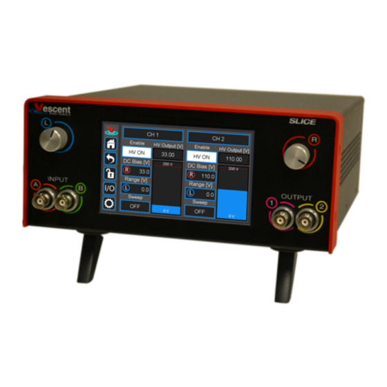
SLICE-DHV Dual-Channel High-Voltage
Amplifier
The SLICE-DHV is a low-noise, high-bandwidth, high-voltage source with DC bias control and
sweep capabilities. It is designed for controlling piezoelectric transducers used for precision
positioning, with particular application to laser frequency stabilization. The high-voltage output
can range from 0 to 200 V, has a voltage noise <500 µV rms, can drive ±200 mA, and has an
unloaded small-signal (±10 V) bandwidth >1 MHz. The SLICE-DHV also has a user-settable
voltage limit for safe operation at voltages less than 200 V.
The SLICE-DHV features two Gain values: G=1 and G=20 for the input modulation signal. When G
is set to 1, the output range is limited to ±10V from the user-settable DC bias voltage. When the
Gain is set to 20, the modulation input signal allows access to the full range of the SLICE-DHV
(0-200 V). When the Gain is set to 1, the SLICE-DHV has better noise performance than when the
Gain is set to 20.
The SLICE-DHV is not recommended for applications that require a large-signal bandwidth greater
than 20 Hz, defined for modulation amplitudes more than 10 V.
Model No. SLICE-DHV
Document Revision: 1
Document Last Updated on 2021/08/26 14:26
Please read
Limited Warranty
Useful Links
Click here for the
Vescent manuals
Click here for the
SLICE-DHV
Click here for the
SLICE-DHV web
Click here for the
Github page for SLICE-DHV firmware revisions
Please check back for added functionality. Contact
corrections, or to request added functionality.
Product Manuals - https://www.vescent.com/manuals/
1/20
and
General Warnings and Cautions
Potential for electrical shock hazard. The
SLICE-DHV can deliver up to 200 V at its
output. Use caution when device is turned
on & enabled.
page.
API.
page.
SLICE-DHV Dual-Channel High-Voltage Amplifier
prior to operating the SLICE-DHV.
sales [at] vescent [dot] com
for questions and
Advertisement
Table of Contents

Summary of Contents for Vescent SLICE-DHV
- Page 1 1, the output range is limited to ±10V from the user-settable DC bias voltage. When the Gain is set to 20, the modulation input signal allows access to the full range of the SLICE-DHV (0-200 V). When the Gain is set to 1, the SLICE-DHV has better noise performance than when the Gain is set to 20.
- Page 2 List of Warning Symbols Warning. Pay special attention to procedures and notes. If procedure is not followed carefully, damage to the SLICE-DHV or devices connected to it may occur. Potential for electrical shock hazard. Important. Pay close attention to manual instructions for optimum results and in order to not damage the device.
-
Page 3: Proper Usage
The SLICE-DHV will accept input line voltages within the ranges shown in table 4. The SLICE-DHV is powered by Vescent's proprietary power supply technology which allows a range of voltage inputs, but retains the noise qualities of a linear supply. Parameter... -
Page 4: Specifications
It is advised that you power off the device before making connections to Always power down the SLICE-DHV completely before making connections to a laser. Never connect or disconnect the SLICE-DHVs to/from a laser with the SLICE-DHV energized. -
Page 5: Front Panel
200 kHz Tab. 7: Approximate bandwidth of SLICE-DHV as a function of load capacitance Front Panel An image of the front panel of the SLICE-DHV is shown in figure 2. The functions and connections are as follows: Channel indicator; touch for... -
Page 6: Rear Panel
Internal ramp amplitude Internal sweep ON/OFF/SWEEP TUNE selection Visual output voltage indicator Signal monitor outputs Fig. 2: Front of SLICE-DHV Rear Panel An image of the rear panel is shown in figure 3. The functions and connections are as follows: Serial Number location High Voltage output (CH 2;... -
Page 7: Screen Navigation
Getting Familiar with the SLICE-DHV The SLICE-DHV is designed to be operated from the touch screen GUI and/or serial commands delivered from a Windows® 10 PC over the USB connection on the back of the chassis. Both the touch screen and serial commands allow access to all of the SLICE-DHV functionality. -
Page 8: Home Screen
field bordered in blue. When a particular field is actively being edited, its border will change to yellow. The ability to edit a yellow-bordered field will automatically time out after about 60 s and the border will turn back to blue. The Home Screen of the SLICE-DHV is shown in figure 4... -
Page 9: Lock Button
2021/08/30 08:42 9/20 SLICE-DHV Dual-Channel High-Voltage Amplifier Fig. 6: Back button Returns to previous screen. Changes will be lost if not accepted before using the Back button. Lock Button Fig. 7: Lock button (shown in unlocked mode) Locks out further modification of operation parameters. - Page 10 Last update: 2021/08/26 14:26 slice:dhv https://www.vescent.com/manuals/doku.php?id=slice:dhv Bias [V] field). By turning the right knob, it is possible to increase (cw) or decrease (ccw) the value of the underlined digit. Turning the left knob will change which digit is editable (cw to move to the right and ccw to move to the left).
- Page 11 Delete Fig. 14: Delete button Deletes last character entered. Enter Fig. 15: Enter button Accepts parameter edits and exits keypad. Extendable Legs The SLICE-DHV has four extendable legs (figure 16). Extending the front legs allows easy viewing from above (figure 1) and extending the rear legs (figure...
- Page 12 This mode allows the modulation input to drive the high voltage output over the entire 0 to 200 V range of the SLICE-DHV. In this mode the DC Bias defaults to zero voltage but can be adjusted to add a DC Bias to the modulation signal if desired. Note that the large-signal bandwidth will be limited when the Gain is set to 20 to less than 20 Hz, but that the small-signal bandwidth (±10V) will be...
- Page 13 2021/08/30 08:42 13/20 SLICE-DHV Dual-Channel High-Voltage Amplifier To change the Gain, touch the CH 1 (or CH 2) field at the top of the channel column. You will be presented with figure 18. Touch the Modulation Mode field to drill down to figure 19...
- Page 14 To set the bias voltage about which the SLICE-DHV will operate on a given channel, touch the DC Bias [V] field on the Home screen. Depending on the length of the touch, either a view similar to figure 10 allowing rotary knob input or a keypad similar to figure 11...
- Page 15 Modulating the SLICE-DHV Output The user can input an analog voltage signal to control the output of the SLICE-DHV. Before introducing a modulation signal, make sure you have selected the desired modulation gain.
- Page 16 22, it is possible to assign the front-panel input as the source of the modulation/control input signal (normally assigned to the SMA connector on the rear panel of the SLICE-DHV). Touching the A Input field displays the menu seen in figure...
-
Page 17: Programmable Output
These front-panel inputs and outputs are mainly intended for monitoring the performance of the SLICE-DHV and as such have slower, less quiet performance than the rear-panel connections. CH 1 can only be assigned to Input 1 and Output A. Likewise CH 2 can only be assigned to Input 2 and Output B. -
Page 18: System Settings
Last update: 2021/08/26 14:26 slice:dhv https://www.vescent.com/manuals/doku.php?id=slice:dhv Fig. 25: Trigger In controls both CH 1 and CH 2 Output Trigger A TTL trigger output in sync with either of the internal ramps can be obtained at the Trigger Out (bubble 7, figure... -
Page 19: Firmware Update
Change the input impedance of the two front-panel input ports. Select either 50 Ω or 1 MΩ. For most applications of the SLICE-DHV, a 1 MΩ impedance should be chosen. SLICE Firmware From time to time, Vescent will upgrade the firmware for controlling the SLICE-DCC. The procedure to upgrade the SLICE-DHV firmware is given here. -
Page 20: Maintenance
Maintenance There are no user-serviceable parts inside this instrument. Refer all repairs to the manufacturer. Work performed by persons not authorized by Vescent Photonics may void the warranty. Located in power receptacle on rear panel, bubble 5 in figure 3...
Need help?
Do you have a question about the SLICE-DHV and is the answer not in the manual?
Questions and answers