
Related Manuals for Berchtold CHROMOPHARE D 650plus

Summary of Contents for Berchtold CHROMOPHARE D 650plus
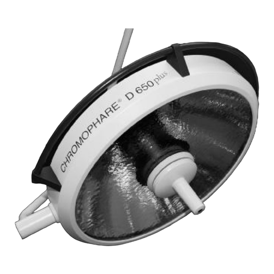
- Page 1 CHROMOPHARE ® D 650 , D 530 , D 500 D 650, D 530, D 500 Service Manual (E) Single Light and Combination Light...
-
Page 2: Table Of Contents
CONTENS PAGE 1. General 6 - 8 Introduction Manufacturer’s notes General information Notes on product responsibility Incoming inspection CE certification Maintenance 2. Commissioning 9 - 10 Range of application Safety information’s Installation Visual and performance check Cleaning, sterilization, disinfection Operation 11 - 25 Components 11 - 13... - Page 3 CONTENS PAGE Technical Data 22 - 29 CHROMOPHARE D 650plus 22 - 23 ® CHROMOPHARE D 530plus, D 500plus 24 - 25 ® CHROMOPHARE D 650 26 - 27 ® CHROMOPHARE D 530, D 500 28 - 29 ® Serial no. identification Spare Part List 30 - 34 CHROMOPHARE®...
- Page 4 CONTENS PAGE 10. Adjustment of weight compensation on the spring arm 67 - 68 10.1 CHROMOPHARE® D 650plus, D 650 (classic cardanic) 10.2 CHROMOPHARE® D 530plus, D 500plus, D 530, D 500 (classic cardanic) 10.3 CHROMOPHARE® D 650plus, D 530plus, D 500plus, D 650, D 530, D 500 (flat cardanic) 11.
- Page 5 CHROMOPHARE® D 530plus/530plus, D 530/530 Control units in power box mounted separately from the OR-Light. 14.24 CHROMOPHARE® D 650plus, D 530plus, D 650, D 530 Wiring diagram for OR-lights with BERCHTOLD camera ChromoVision® AF II 15. Power requirements 15.1 List of fuse specifications 15.2...
-
Page 6: General
1. GENERAL 1.1 Introduction The CHROMOPHARE® D 650plus, D 530plus and D 500plus consists of a swivel arm support, a lamp housing and a flange tube. The lamp housing is fixed to a cardanic-type support (vertical gimbal joint, horizontal gimbal joint) and can be rotated, swivelled and tilted in any direction. -
Page 7: Manufacturer's Notes
BERCHTOLD representative or to BERCHTOLD directly. When an appliance or parts of an appliance are returned to BERCHTOLD or to a BERCHTOLD service agent, the original packaging should be used where possible. The following accompanying documentation must be at- tached: owner’s name and address, equipment number (see type plate), description of the defect. -
Page 8: Ce Certification
1.6 EC Certification The equipment complies with the requirements of the EC guideline regarding medical products, 93/42/EEC as well as the UL guidelines. 1.7 Maintenance The CHROMOPHARE® lights should be serviced once a year (maintenance contract). The Maintenance constist the steps as listed in the range of maintenance page 71. 2. -
Page 9: Installation
Mounting and installation of the CHROMOPHARE® lights must be in accordance with BERCHTOLD’s “Mounting instructions for ceiling lights” and must only be performed by BERCHTOLD employees or by instal- lation companies authorized by BERCHTOLD. The installation of lights on the ceiling of the operating room must be performed in accordance with BERCHTOLD’s “Ceiling anchor plate and spacer block”... -
Page 10: Cleaning, Sterilization, Disinfection
When filling the autoclave ensure that the open side of the handles are face down. The sleeves must lie free and must not come into contact with any other items being sterilized. Hot-air sterilization is not recommended by BERCHTOLD. However, if it is necessary, the handles should be sterilized loose at 134° C; 3 minutes. -
Page 11: Operation
3. OPERATION 3.1 Components 3.1.1 CHROMOPHARE® D 650plus/650plus, D 650/650 (classic cardanic) Ceiling cover Lamp housing hood Flange tube dia. 125 mm Lamp frame Horizontal swivel arm Light emission lens Vertical spring arm Sterilizable hand grip sleeves Vertical gimbal joint Rail (encircling hand grip) Horizontal gimbal joint Control unit... -
Page 12: Chromophare® D 530Plus/530Plus, D 530/530 (Classic Cardanic)
3.1.3 CHROMOPHARE® D 530plus/530plus, D 530/530 (classic cardanic) Ceiling cover Lamp housing hood Flange tube dia. 125 mm Lamp frame Horizontal swivel arm Light emission lens Vertical spring arm Sterilizable hand grip sleeves Vertical gimbal joint Rail (encircling hand grip) Horizontal gimbal joint Control unit 3.1.4 CHROMOPHARE®... -
Page 13: Chromophare® D 500Plus, D 500 (Classic Cardanic)
3.1.5 CHROMOPHARE® D 500plus, D 500 (classic cardanic) 1 Ceiling cover 2 Flange tube dia. 65 mm 3 Horizontal swivel arm 4 Vertical spring arm 5 Vertical gimbal joint 6 Horizontal gimbal joint 7 Lamp housing hood 8 Lamp frame 9 Light emission lens 10 Sterilizable hand grip sleeves 11 On/Off switch... -
Page 14: Notes On Operation
3.2 Notes on operation 3.2.1 Setting the control unit functions 3.2.1.1 CHROMOPHARE® D 650plus, D 650 The following functions can be controlled by the control unit: • On/off • Intensity of illumination Options: • Electronic light field adjustment - only for LFN •... - Page 15 4 By pressing and holding down Key 4 (DARK) the illuminance is continuously reduced down to the minimum value. Repeated short presses decrease the illuminance in steps. 5 If the indicator light shows red, there is a fault in the control unit electronics 6 Only with the EndoLite®...
-
Page 16: Chromophare® D 530Plus, D 530
3.2.1.2 CHROMOPHARE® D 530plus, D 530 The following functions can be controlled by the control unit: • On/off • Intensity of illumination Options: • Switch over to EndoLite® surround light - switch to operating light - only with EndoLite® option 1 ON Switch on the light 2 OFF... -
Page 17: Chromophare ® D 500Plus, D 500
7 Only with the EndoLite® option. By pressing Key 7 (OP light) the EndoLite® surround lighting is switched off and the surgical area lighting is switched on again. 3.2.1.3 CHROMOPHARE® D 500plus, D 500 The following functions can be controlled by the control unit: •... -
Page 18: Adjusting The Field Size With The Sterizable Hand Grip
3.2.2 Adjusting the field size with the centre hand grip By turning the sterilizable centre hand grip the size of the light field is changed. By turning the hand grip in the clockwise direction the light field is enlarged, by turning anti-clockwise the light field is reduced. The surgeon must perform the optimum field setting himself in accordance with the size of the operation opening. -
Page 19: Light Field Plotting Model Lfn (Option Only D 650Plus, D 650)
3.2.6 Light field plotting model LFN (option only D 650plus, D 650) The CHROMOPHARE D 650plus und D 650 can be ordered with an LFN light field plotter as an option. The ® light field plotter is an electronic control system, which moves the lamps by electric motor. An infrared beam which is reflected by a reflector disk controls the light field plotter. -
Page 20: System Variants
3.4 Systemvarianten The CHROMOPHARE® generation D is available in the following system variants: 1. CHROMOPHARE® D 650plus as a single light 2. CHROMOPHARE® D 650plus as a double and a triple light 3. CHROMOPHARE® D 650plus as a combination light with D 530plus 4. - Page 21 Switch the lighting system on and check that the lamp is on and the red indicator light is off. Note! Only use original BERCHTOLD halogen bulbs. If other bulbs are used, all guarantees regarding per- formance and operation will lapse. CHROMOPHARE® D 650plus, D 530plus, D 500plus, D 650, D 530, D 500 Service Manual (E)
-
Page 22: Technical Data
4. TECHNICAL DATA 4.1 CHROMOPHARE® D 650plus Light technical data D 650plus Reflector system Polygon reflector Colour temperature 4500 K 3600 K Intensity Ec at 1 m [klx] Intensity control [klx] 70 - 130 70 - 150 Total radiant power at max intensity 485 W/m 555 W/m Total radiant power/intensity Ec [mW/m... - Page 23 Dimensions D 650plus Diameter of light body 65 cm Diameter of Polygon Reflectors 58,5 cm Light emission surface (glass surface) 2370 cm Max. swivel radius 237 cm Lowest position of light body 128 cm Highest position of light body 226 cm Clearance (single light) 200 cm at 265 cm finished ceiling Weight / Torque...
-
Page 24: Chromophare ® D 530Plus, D 500Plus
4.2 CHROMOPHARE D 530plus, D 500plus ® Light technical data D 530plus D 500plus Reflector system Polygon reflector Colour temperature 4500plus K 3600 K 4500plus K 3600 K Intensity Ec at 1 m [klx] Intensity control [klx] 55 - 110 70 - 140 Total radiant power at max intensity 410 W/m... - Page 25 Dimensions D 530plus D 500plus Diameter of light body 52 cm Diameter of Polygon Reflectors 45,5 cm Light emission surface (glass surface) 1374 cm Max. swivel radius 231 cm Lowest position of light body 130 cm Highest position of light body 219 cm Clearance (single light) 200 cm at 245 cm finished ceiling...
- Page 26 4.3 CHROMOPHARE D 650 ® Light technical data D 650 Reflector system Polygon reflector Colour temperature 4500 K 3600 K Intensity Ec at 1 m [klx] Intensity control [klx] 70 - 140 70 - 140 Total radiant power at max intensity 520 W/m Total radiant power/intensity Ec [mW/m lux]...
- Page 27 General data D 650 Halogen bulb 22,8 V / 250 W 22,8 V / 150 W Order no. CZ 907-22 CZ 908-22 Life time of halogen bulb 1000 h Automatic switch over to reserve bulb Dimensions Diameter of light body 65 cm Diameter of Polygon Reflectors 58,5 cm...
-
Page 28: Chromophare ® D 530, D 500
4.4 CHROMOPHARE D 530, D 500 ® Light technical data D 530 D 500 Reflector system Polygon reflector Colour temperature 4500 K 3600 K 4500 K 3600 K Intensity Ec at 1 m [klx] Intensity control [klx] 55 - 110 Total radiant power at max intensity 410 W/m 336 W/m... - Page 29 General data D 530 D 500 Halogen bulb at colour temperature 4500 K 22,8 V / 150 W Order no. CZ 908-22 Halogen bulb at colour temperature 3600 K 22,8 V / 110 W Order no. CZ 905-22 Life time of halogen bulb 1000 h Automatic switch over to reserve bulb Dimensions...
-
Page 30: Serial No. Identification
5. SERIAL NO. IDENTIFICATION Type plate (A) 1 Version number 2 Variant 3 Manufacturing year 4 Serial number 6. SPARE PART LIST 6.1 CHROMOPHARE® D 650plus, D 650 Description Part no. Picture on page Filtering board 65606 Reverse polarity protection 65601 Light intensity power circuit board 65604... - Page 31 Description Part no. Picture on page Male sliding contact 65241 Female sliding contact 20002 Brake screw 64103 Cross recessed raised cheese head screw 45396 Mortise screw 64126 Brake screw 42805 Positioning screw 43009 Brake screw 42803 Ejot screw 64669 Hood 64101 Sealing rubber 64677...
- Page 32 Description Part no. Picture on page O-ring 64203 Cover 62418 49 / 50 Connection board for Standard 64162 Holder for bulb with connecting cables 64146 Housing for touch control board for Standard 62407 Touch control board with foil for Standard 68823 Touch control board with foil for Standard with EndoLite®...
-
Page 33: Chromophare® D 530Plus, D 500Plus, D 530, D 500
6.2 CHROMOPHARE® D 530plus, D 500plus, D 530, D 500 Description Part no. Picture on page Filtering board 65606 Reverse polarity protection 65601 Light intensity power circuit board 65604 Hexagon socket countersunk head screw Locking pin 64174 Sliding contact 64186 Brake screw 38821 Cross recessed raised cheese head screw... - Page 34 Description Part no. Picture on page Bumper, left 66320 Bumper, right 66319 Housing for touch control board for D 530plus, D 530 62407 Touch control board for D 530plus, D 530 Standard 68823 Touch control board for D 530plus, D 530 Standard with 68824 EndoLite®...
-
Page 35: Transformers
7. TRANSFORMERS 7.1 CHROMOPHARE® D 650 CHROMOPHARE® D 650plus, D 530plus, D 500plus Mounting separate from the ceiling tube, distance of transformer to ceiling tube over 20 m CB 502-40 Transformer mounted on flange tube 220/230/240V / 400 VA CB 505-40 Transformer mounted separately 220/230/240V / 400 VA CB 502-42 Transformer mounted on flange tube 100/120/127 V / 400 VA CB 505-42 Transformer mounted separately 100/120/127 V / 400 VA How to proceed the transformer adjustment (with topped filtering board):... - Page 36 Primary terminal main voltage Secondary terminal approx. A.C. voltage approx. D.C. voltage at filtering board input at filtering board output Trafo CB 502-42 or CB 505-42 100 V 120 V 127 V Trafo CB 502-40 or CB 505-40 220 V 230 V 240 V A.C.
-
Page 37: Chromophare® D 650Plus, D 530Plus, D 500Plus, D 530, D 500
7.2 CHROMOPHARE® D 650plus, D 530plus, D 500plus, D 530, D 500 Mounting on the ceiling tube and separate from the ceiling tube, distance of transformer to ceiling tube 20 m CB 502-32 Transformer mounted on flange tube 220/230 V/240 VA CB 505-32 Transformer mounted separately 220/230 V/240 VA CB 502-30... - Page 38 Primary terminal main voltage Secondary terminal approx. A.C. voltage approx. D.C. voltage at filtering board input at filtering board output Trafo CB 502-30 or CB 505-30 100 V 120 V 127 V Trafo CB 502-32 or CB 505-32 220 V 230 V 240 V A.C.
- Page 39 Drilling measurements mounting plate - supply unit Planting depth min 200 mm CHROMOPHARE® D 650plus, D 530plus, D 500plus, D 650, D 530, D 500 Service Manual (E)
-
Page 40: Graphic Spare Part Description
8. GRAPHIC SPARE PART DESCRIPTION 8.1 CHROMOPHARE® generation D complete Filtering board, part no. 65606 Note! Due to the EMV conditions, the filtering board has gen- erally to be connected and installed as near as possible to the transformer. Please consider that the installed filtering board should be able to eliminate heat through a large surface. - Page 41 All models with BERCHTOLD wall box have the re- verse polarity protection module inside the wall box, where it is preconnected to the electronics.
- Page 42 Light intensity power circuit board, part no. 65604 Attention! No A.C. voltage must be fed into the electronics. A direct supply of A.C. voltage always destroys the light electronics. If only A.C. voltage is available, the filtering board (part no. 65606) has always to be preconnected to the light electronics.
- Page 43 1 5 x Hexagon socket countersunk head screw, 8 2 x cross recessed countersunk head screw, part no. 284, minimal torque 23 Nm part no. 235 2 Locking pin, part no. 64174 9 Male sliding contact, part no. 65241 3 Sliding contact, part no. 64186 10 Female sliding contact, part no.
- Page 44 1 Brake screw, part no. 42805 2 Security screw, part no. 43009 1 Security screw, part no. 43009 2 Brake screw, part no. 42803 3 Ejot screw, part no. 64669 1 Hood D 650plus, D 650, part no. 64101 Hood D 530plus, D 500plus, D 530, D 500 part no.
- Page 45 Test adapter for check of the halogen bulb supply volt- age and check of the switch over function to reserve bulb part no. 50574 Wiring harness, from electronic to reflector connector, part no. 65769 1 Screw, part no. 68071 2 Brake screw M5x5, part no. 68072 3 Countersunk head screw M3x12, part no.
-
Page 46: Chromophare® D 650Plus, D 650
1 Bumper left, part no. 66320 2 Bumper right, part no. 66319 Security lock – spring balanced arm, part no. 20010 8.2 CHROMOPHARE® D 650plus, D 650 1 Protection bush, part no. 20011 2 Washer, part no. 24197 3 Screw, part no. 11656 4 Security lock –... - Page 47 1 Guiding rod, with pressed socket for banana plug dia. 4 mm part no. 64778 Filter glass assembly D 650plus, part no 68618 Filter glass assembly D 650, part no. 64157 D.C. motor with cable and connector, mounted in the focusing mechanism, part no.
- Page 48 Control circuit board for centre positioning of main bulb, part no. 64176 CHROMOPHARE® D 650plus, D 530plus, D 500plus, D 650, D 530, D 500 Service Manual (E)
-
Page 49: Chromophare® D 650Plus, D 650 Version Standard And Endolite
8.3 CHROMOPHARE® D 650plus, D 650 version Standard and EndoLite® Focusing mechanism for Standard and EndoLite® without halogen bulbs, part no. 64163 1 Guiding screw, part no. 64152 2 O-ring, part no. 64203 3 Cover, part no. 62418 4 Connection board Standard, part no. 64162 5 Holder for bulb with connecting cables without halogen bulbs, part no. -
Page 50: Chromophare® D 650Plus, D 530Plus, D 650, D 530
Cover, part no. 62418 8.4 CHROMOPHARE® D 650plus, D 530plus, D 650, D 530 Housing for touch control board, part no. 62407 Touch control board with foil for Standard, part no. 68823 CHROMOPHARE® D 650plus, D 530plus, D 500plus, D 650, D 530, D 500 Service Manual (E) - Page 51 Touch control board with foil for Standard with EndoLite® part no. 68824 8.5 CHROMOPHARE® D 650plus, D 530plus, D 650, D 530 version Standard without EndoLite® Reserve bulb switch over circuit board without EndoLite® (mounted in the light body) part no. 65610 4 to reserve bulb (RL) 5 (+) input, coming from light intensity power circuit board (LAIN +)
-
Page 52: Chromophare® D 650Plus, D 650 Version Light Field Plotting Model Lfn
8.6 CHROMOPHARE® D 650plus, D 650 version light field plotting model LFN Focusing mechanism for LFN and LFN with EndoLite® without halogen bulbs, part no. 64673 1 Holder for bulb with connecting cables without halogen bulbs, part no. 64146 2 IR-module, part no. 65643 3 Pressure spring, part no. - Page 53 Cover, part no. 64194 IR-module, part no. 65643 Motor for LFN, part no. 54860 CHROMOPHARE® D 650plus, D 530plus, D 500plus, D 650, D 530, D 500 Service Manual (E)
- Page 54 1 Gearwheel, part no. 54849 2 Ring for sliding clutch, part no. 54809 LFN control, part no. 65608 Housing for touch control board for LFN and LFN with EndoLite® part no. 62401 Touch control board with foil for LFN part no. 68825 CHROMOPHARE®...
-
Page 55: Chromophare® D 650Plus, D 530Plus, D 650, D 530 Version With Endolite
Touch control board with foil for LFN with EndoLite® part no. 68826 8.7 CHROMOPHARE® D 650plus, D 530plus, D 650, D 530 version with EndoLite® EndoLite®, spare bulb 12V/20W, with glass disc and reflector, part no. CZ 960-12 Reserve bulb switch over circuit board with EndoLite®... -
Page 56: Chromophare® D 530Plus, D 500Plus, D 530, D 500
A to EndoLite®, max. 11,0 V A.C. / D.C. 8.8 CHROMOPHARE® D 530plus, D 500plus, D 530, D 500 1 Protection bush, part no. 20011 2 Washer, part no. 24197 3 Screw, part no. 11656 4 Security lock – spring balanced arm, (not visible) part no. - Page 57 1 D 530plus, D 530: Guiding rod, with pressed socket for banana plug dia. 4 mm part no. 66406 D 500plus, D 500: Guiding rod, with pressed socket for banana plug dia. 4 mm part no. 66405 D 530plus, D 530: filter glass assembly, part no.
-
Page 58: Chromophare® D 530Plus, D 530 Version Standard And Endolite
8.9 CHROMOPHARE® D 530plus, D 530 version Standard and EndoLite® Focusing mechanism for Standard and EndoLite® without halogen bulbs, part no.66421 1 Holder for bulb, part no. 64146 2 Screw, lower stop, part no. 66422 3 Screw, upper stop, part no. 66423 4 Cover, part no. -
Page 59: Chromophare® D 500Plus, D 500 Version Standard
8.10 CHROMOPHARE® D 500plus, D 500 version Standard Focusing mechanism for Standard without halogen bulbs, part no. 66419 1 Holder for bulb, part no. 64146 2 Cover, part no. 64418 3 Knurled screw, part no. 64142 4 O-ring, part no. 64203 Focusing mechanism D 500plus, D 500 1 Threaded rod, part no. - Page 60 Connection board for Standard, part no. 64162 HL = Main bulb RL = Reserve bulb HL/RL = Main and reserve bulb 1 Touch control board for D 500plus, D 500, part no. 66417 2 Housing for touch control board for D 500plus, D 500, part no.
-
Page 61: Test And Adjustment Points
9. TEST AND ADJUSTMENT POINTS 9.1 Test points CHROMOPHARE® D 650 TP 1 Terminal block 24 V D.C. loaded, tolerance + 1.5 / - 0.3 V TP 2 Sliding contact 24 V D.C. loaded, tolerance + 1.5 / - 0.3 V TP 3 Sliding ring 23.8 V D.C. -
Page 62: Chromophare® D 650Plus, D 650 (Classic Cardanic)
9.3.1 CHROMOPHARE® D 650plus, D 650 9.3.2 CHROMOPHARE® D 650plus, D 650 (classic cardanic) (flat cardanic) Brake screw Spring adjustment, see page 65 - 66 TP Test points, see page 59 Height movement, see page 66 9.3.3 CHROMOPHARE® D 650plus/530plus, D 650/530 (classic cardanic) Brake screw Spring adjustment, see page 65 - 66 TP Test points, see page 59... -
Page 63: Chromophare® D 650Plus/530Plus, D 650/530 (Flat Cardanic)
9.3.4 CHROMOPHARE® D 650plus/530plus, D 650/530 (flat Kardanik) Brake screw Spring adjustment, see page 65 - 66 TP Test points, see page 59 Height movement, see page 66 9.3.5 CHROMOPHARE® D 530plus, D 530 9.3.6 CHROMOPHARE® D 530plus, D 530 (classic cardanic) (flat cardanic) Brake screw... -
Page 64: Chromophare® D 500Plus, D 500 (Classic Cardanic)
9.3.7 CHROMOPHARE® D 500plus, D 500 9.3.8 CHROMOPHARE® D 500plus, D 500 (classic cardanic) (flat cardanic) Brake screw Spring adjustment, see page 65 - 66 TP Test points, see page 59 Height movement, see page 66 9.3.9 CHROMOPHARE® D 530plus/530plus, D 530/530 (classic cardanic) Brake screw Spring adjustment, see page 65 - 66 TP Test points, see page 59... -
Page 65: Chromophare® D 530Plus/530Plus, D 530/530 (Flat Cardanic)
9.3.10 CHROMOPHARE® D 530plus/530plus, D 530/530 (flat cardanic) Brake screw Spring adjustment, see page 65 - 66 TP Test points, see page 59 Height movement, see page 66 9.4 Adjustment points for halogen bulb and EndoLite® bulb voltage (only D 650plus, D 530plus, D 650, D 530) Back side of touch control board Part no. -
Page 66: Adjustment Points For Halogen Bulb- And Endolite ® Bulb Voltage
Attention: For correct bulb voltage setting please notice! If the light intensity power circuit board is installed in separate wall box please take also the voltage drop of the cable into consideration. If the terminal voltage under load on the ceiling tube is higher than 24.5 V D.C. (main or supplementary supply), an electronically alignment must be done. - Page 67 10. ADJUSTMENT OF WEIGHT COMPENSATION ON THE SPRING ARM 10.1 CHROMOPHARE® D 650plus, D 650 (classic cardanic) Remove both screws by using a 2 mm Allen key. Loosen the covers of the spring-balanced support arm. Adjustment: Light head drifts upward: Move the acrobat arm upward or downward as far as the circu- lar nut becomes visible in one of the two windows.
- Page 68 10.3 CHROMOPHARE® D 650plus, D 530plus, D 500plus, D 650, D 530, D 500 (flat cardanic) Remove the cover plate by using a Phillips screwdriver. Adjustment: Light head drifts upward: Move the acrobat arm upward or downward as far as the circu- lar nut becomes visible in one of the two windows.
- Page 69 12. BRAKE ADJUSTMENTS Tools required: Slotted screwdriver, large Allen key 3 mm Allen key 2,5 mm The braking effect of the individual joints must be adjusted so that the lamp housing remains in the required position. If a sus- pension arm of the OP light drifts away, the appropriate brake screw must be tightened.
- Page 70 Cardan joint (flat cardanic) The mobility of the cardan joint can be adjusted with the brake screw. (Allen key 2.5 mm) + ð Clockwise − ð Anti-clockwise Attention: + ð increase friction − ð decrease friction CHROMOPHARE® D 650plus, D 530plus, D 500plus, D 650, D 530, D 500 Service Manual (E)
- Page 71 Tension of the support arm springs Support screws of the central positioning shaft / tighten the ceiling tube (min 23 Nm) Check the means of illumination i.e. the original BERCHTOLD halogen bulb (Voltage, Watts) Check the contacts of the bulb supports...
- Page 72 14. WIRING DIAGRAMS 14.1 CHROMOPHARE® D 650plus, D 650 Transformer mounted on the ceiling tube CHROMOPHARE® D 650plus, D 530plus, D 500plus, D 650, D 530, D 500 Service Manual (E)
- Page 73 14.2 CHROMOPHARE® D 650plus, D 650 Transformer and emergency relays mounted on the ceiling tube CHROMOPHARE® D 650plus, D 530plus, D 500plus, D 650, D 530, D 500 Service Manual (E)
- Page 74 14.3 CHROMOPHARE® D 650plus, D 650 Power supply mounted in a cut-out cabinet CHROMOPHARE® D 650plus, D 530plus, D 500plus, D 650, D 530, D 500 Service Manual (E)
- Page 75 14.4 CHROMOPHARE® D 650plus, D 650 Control unit in “Power box” mounted separately from the OR-Light CHROMOPHARE® D 650plus, D 530plus, D 500plus, D 650, D 530, D 500 Service Manual (E)
- Page 76 14.5 CHROMOPHARE® D 650plus, D 650 Touch panel for light intensity is mounted in the wall panel CHROMOPHARE® D 650plus, D 530plus, D 500plus, D 650, D 530, D 500 Service Manual (E)
- Page 77 14.6 CHROMOPHARE® D 530plus, D 500plus, D 530, D 500 Transformer mounted on the ceiling tube CHROMOPHARE® D 650plus, D 530plus, D 500plus, D 650, D 530, D 500 Service Manual (E)
- Page 78 14.7 CHROMOPHARE® D 530plus, D 500plus, D 530, D 500 Transformer and emergency relays mounted on the ceiling tube CHROMOPHARE® D 650plus, D 530plus, D 500plus, D 650, D 530, D 500 Service Manual (E)
- Page 79 14.8 CHROMOPHARE® D 530plus, D 500plus, D 530, D 500 Power supply mounted in a cut-out cabinet CHROMOPHARE® D 650plus, D 530plus, D 500plus, D 650, D 530, D 500 Service Manual (E)
- Page 80 14.9 CHROMOPHARE® D 530plus, D 500plus, D 530, D 500 Control unit in “Power Box” mounted separately from the OR-Light CHROMOPHARE® D 650plus, D 530plus, D 500plus, D 650, D 530, D 500 Service Manual (E)
- Page 81 14.10 CHROMOPHARE® D 530plus, D 500plus, D 530, D 500 Touch panel for light intensity is mounted in the wall panel CHROMOPHARE® D 650plus, D 530plus, D 500plus, D 650, D 530, D 500 Service Manual (E)
- Page 82 14.11 CHROMOPHARE® D 650plus/650plus, D 650/650 Transformers mounted on the ceiling tube CHROMOPHARE® D 650plus, D 530plus, D 500plus, D 650, D 530, D 500 Service Manual (E)
- Page 83 14.12 CHROMOPHARE® D 650plus/650plus, D 650/650 Transformers and emergency relays mounted on the ceiling tube CHROMOPHARE® D 650plus, D 530plus, D 500plus, D 650, D 530, D 500 Service Manual (E)
- Page 84 14.13 CHROMOPHARE® D 650plus/650plus, D 650/650 Power supply mounted in a cut-out cabinet CHROMOPHARE® D 650plus, D 530plus, D 500plus, D 650, D 530, D 500 Service Manual (E)
- Page 85 14.14 CHROMOPHARE® D 650plus/650plus, D 650/650 Control units in “Power Box” mounted separately from the OR-Light CHROMOPHARE® D 650plus, D 530plus, D 500plus, D 650, D 530, D 500 Service Manual (E)
- Page 86 14.15 CHROMOPHARE® D 650plus/530plus, D 650plus/500plus, D 650/530, D 650/500 Transformers mounted on the ceiling tube CHROMOPHARE® D 650plus, D 530plus, D 500plus, D 650, D 530, D 500 Service Manual (E)
- Page 87 14.16 CHROMOPHARE® D 650plus/530plus, D 650plus/500plus, D 650/530, D 650/500 Transformers and emergency relays mounted on the ceiling tube CHROMOPHARE® D 650plus, D 530plus, D 500plus, D 650, D 530, D 500 Service Manual (E)
- Page 88 14.17 CHROMOPHARE® D 650plus/530plus, D 650plus/500plus, D 650/530, D 650/500 Power supply mounted in a cut-out cabinet CHROMOPHARE® D 650plus, D 530plus, D 500plus, D 650, D 530, D 500 Service Manual (E)
- Page 89 14.18 CHROMOPHARE® D 650plus/530plus, D 650/530 Control units in “Power Box” mounted separately from the OR-Light CHROMOPHARE® D 650plus, D 530plus, D 500plus, D 650, D 530, D 500 Service Manual (E)
- Page 90 14.19 CHROMOPHARE® D 650plus/500plus, D 650/500 Control units in “Power Box” mounted separately from the OR-Light CHROMOPHARE® D 650plus, D 530plus, D 500plus, D 650, D 530, D 500 Service Manual (E)
- Page 91 14.20 CHROMOPHARE® D 530plus/530plus, D 500plus/500plus, D 530/530, D 500/500 Transformers mounted on the ceiling tube CHROMOPHARE® D 650plus, D 530plus, D 500plus, D 650, D 530, D 500 Service Manual (E)
- Page 92 14.21 CHROMOPHARE® D 530plus/530plus, D 500plus/500plus, D 530/530, D 500/500 Transformers and emergency relays mounted on the ceiling tube CHROMOPHARE® D 650plus, D 530plus, D 500plus, D 650, D 530, D 500 Service Manual (E)
- Page 93 14.22 CHROMOPHARE® D 530plus/530plus, D 500plus/500plus, D 530/530, D 500/500 Power supply mounted in a cut-out cabinet CHROMOPHARE® D 650plus, D 530plus, D 500plus, D 650, D 530, D 500 Service Manual (E)
- Page 94 14.23 CHROMOPHARE® D 530plus/530plus, D 530/530 Control units in “Power Box” mounted separately from the OR-Light CHROMOPHARE® D 650plus, D 530plus, D 500plus, D 650, D 530, D 500 Service Manual (E)
- Page 95 14.24 CHROMOPHARE® D 650plus, D 530plus, D 650, D 530 Wiring diagram for OR-lights with BERCHTOLD camera ChromoVision® AF II CHROMOPHARE® D 650plus, D 530plus, D 500plus, D 650, D 530, D 500 Service Manual (E)
- Page 96 15. POWER REQUIREMENTS 15.1 List of fuse specifications Fuse values to be installed on-site [A] 220 – 240 V 110 – 120 V Light Battery Battery F2/F3 F2/F3 D 500plus D 530plus D 650plus D 500 D 530 D 650 All fuse slow blow 15.2 List of terminal voltages The terminal voltages specified in table below must be provided on the flanged tube of the CHROMOPHARE®...
- Page 97 CHROMOPHARE® D 650plus, D 530plus, D 500plus, D 650, D 530, D 500 Service Manual (E)
- Page 98 Tel. (+49) 7461 / 181-217 e-mail: Info@Berchtold.de Fax (+49) 7461 / 181-311 56 791/M-S/B/03.2003 © BERCHTOLD GmbH & Co.KG Reproduction including excerpts, prohibited. Alterations in technology and design reserved. CHROMOPHARE® D 650plus, D 530plus, D 500plus, D 650, D 530, D 500 Service Manual (E)
Need help?
Do you have a question about the CHROMOPHARE D 650plus and is the answer not in the manual?
Questions and answers