Table of Contents
Advertisement
Quick Links
Advertisement
Table of Contents

Subscribe to Our Youtube Channel
Related Manuals for Carrier TruVu MPC


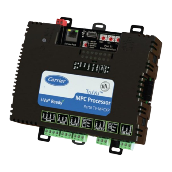
Summary of Contents for Carrier TruVu MPC
- Page 1 ™ ™ CARRIER CORPORATION ©2021 · Catalog No. 11-808-691-01 · 9/20/2021...
- Page 2 Verify that you have the most current version of this document from www.hvacpartners.com, the Carrier Partner Community website, or your local Carrier office. Important changes are listed in Document revision history at the end of this document. CARRIER CORPORATION ©2021. All rights reserved throughout the world. i-Vu is a registered trademark of Carrier...
-
Page 3: Table Of Contents
Touchscreen devices ............................6 To mount the TV-MPCXP ............................7 To attach I/O expanders ............................9 TruVu MPC I/O expander configurations ......................9 To attach TruVu MPC I/O expanders....................... 13 To attach MPC Open XPIO expanders......................14 Wiring for power ..............................15 To wire for power ............................... - Page 4 Contents To communicate locally through the Rnet port ....................52 Troubleshooting ..............................53 LEDs ..................................53 To get a Module Status report ......................... 55 To get a Device Log ............................55 To get the TV-MPCXP's serial number ......................56 To replace the TV-MPCXP's fuses ........................56 To take the TV-MPCXP out of service ......................
-
Page 5: What Is The Truvu™ Mpc Processor
Can serve as a gateway that can act as a: • Master or slave on a Modbus serial network • Server or client on a Modbus TCP/IP network TruVu™ MPC Processor CARRIER CORPORATION ©2021 Installation and Start-up Guide All rights reserved... -
Page 6: Specifications
>.driverx Maximum number of control programs* Maximum number of BACnet objects* 12000 Third-party BACnet integration points 1500 Third-party Modbus integration points * Depends on available memory. TruVu™ MPC Processor CARRIER CORPORATION ©2021 Installation and Start-up Guide All rights reserved... - Page 7 Real-time clock Real-time clock keeps track of time in the event of a power failure for up to 3 days. TruVu™ MPC Processor CARRIER CORPORATION ©2021 Installation and Start-up Guide All rights reserved...
- Page 8 1 lb. (0.45 kg) BACnet support Conforms to the BACnet Building Controller (B-BC) Standard Device Profile as defined in ANSI/ASHRAE Standard 135-2012 (BACnet) Annex L, Protocol Revision TruVu™ MPC Processor CARRIER CORPORATION ©2021 Installation and Start-up Guide All rights reserved...
-
Page 9: Zone Sensors
Rnet, verify that the total current draw of the sensors does not exceed the controller's Rnet power. See the sensor's Installation and Start-up Guide to determine the power required. TruVu™ MPC Processor CARRIER CORPORATION ©2021 Installation and Start-up Guide All rights reserved... -
Page 10: Touchscreen Devices
• The TruVu™ ET Display requires a 24 Vdc external power source. CAUTION A touchscreen device can share a power supply with the Carrier controller if: • The power source shared by the controller and Equipment Touch is AC power. -
Page 11: To Mount The Tv-Mpcxp
Place the controller on the DIN rail so that the rail is in the trough on the back of the controller. Push the center tabs towards the controller until you hear them click. Pull gently on the controller to verify that it is locked in place. TruVu™ MPC Processor CARRIER CORPORATION ©2021 Installation and Start-up Guide All rights reserved... - Page 12 Insert #6 screws through the mounting tabs. Use no more than 8 in.lbs. torque to secure plastic tab to mounting surface. 7.1 in. (18.03 cm) 6.95 in. (17.65 cm) 6.45 in. (16.38 cm) 4.1 in. (10.4 cm) Depth: 2.09 in (5.31 cm) TruVu™ MPC Processor CARRIER CORPORATION ©2021 Installation and Start-up Guide All rights reserved...
-
Page 13: To Attach I/O Expanders
To attach MPC Open XPIO expanders (page 14) The expander's Installation and Start-up Guide TruVu MPC I/O expander configurations The expanders' outputs return to their unconfigured state if they are removed from the program or the program is deleted from the controller. Also, outputs time out and return to their unconfigured or off state after two minutes of inactivity. - Page 14 The TV-MPCXP is powered by a Class 2 power source. Take appropriate isolation measures when mounting it in a control panel where non-Class 2 circuits are present. • Carrier controllers can share a power supply as long as you: • Maintain the same polarity.
- Page 15 MPC I/O expanders you have. The following configuration shows a combination of connections using the I/O bus edge connector and daisy- chained wiring to the I/O Bus ports. TruVu™ MPC Processor CARRIER CORPORATION ©2021 Installation and Start-up Guide All rights reserved...
- Page 16 I/O bus edge connector that provides power and communication. The configuration also shows a combination of connections using the edge connector and wiring to the I/O Bus ports. TruVu™ MPC Processor CARRIER CORPORATION ©2021 Installation and Start-up Guide All rights reserved...
-
Page 17: To Attach Truvu Mpc I/O Expanders
To attach I/O expanders To attach TruVu MPC I/O expanders An TruVu MPC I/O expander can be directly-connected to the TV-MPCXP's I/O bus edge connector or wired to the TV-MPCXP's I/O Bus port. To connect the TruVu MPC I/O expander to the I/O bus edge connector NOTE The following instructions assume that the controller is already mounted either on a DIN rail or using screws. -
Page 18: To Attach Mpc Open Xpio Expanders
NOTE You must set the Xnet baud rate to 500 kbps in the i-Vu® interface on the driver's I/O Bus and Xnet Expanders page. See Adjusting TV-MPCXP driver properties (page 33). TruVu™ MPC Processor CARRIER CORPORATION ©2021 Installation and Start-up Guide All rights reserved... -
Page 19: Wiring For Power
The TV-MPCXP is powered by a Class 2 power source. Take appropriate isolation measures when mounting it in a control panel where non-Class 2 circuits are present. • Carrier controllers can share a power supply as long as you: • Maintain the same polarity. -
Page 20: Addressing The Tv-Mpcxp
Navigate to http://local.access or http://169.254.1.1 to see the Service Port controller setup pages. See To set up the controller through the Service Port (page 47) for general information on using the controller setup pages. TruVu™ MPC Processor CARRIER CORPORATION ©2021 Installation and Start-up Guide All rights reserved... -
Page 21: Rotary Switch Settings
EXAMPLE The switches below are set to 125. CAUTION Do not leave the rotary switches set at 0 (the factory default). The TV-MPCXP cannot be discovered if the rotary switches are left at 0. TruVu™ MPC Processor CARRIER CORPORATION ©2021 Installation and Start-up Guide All rights reserved... -
Page 22: To Set Up Autobaud
Autobaud does not work unless there is a device on the network, whether Carrier or third party, that has the baud rate already set. You can manually set the baud rate on more than one device, as long as the rate is the same for every device. -
Page 23: To Set The Ip Address
On the controller setup Ports tab under IP Port, select Custom Static. Enter the IP Address, Subnet Mask, and Default Gateway addresses that the network administrator gave you. Click Save. TruVu™ MPC Processor CARRIER CORPORATION ©2021 Installation and Start-up Guide All rights reserved... - Page 24 Content. See the i-Vu® Help for more information. NOTE The default address is an intranet address. Data packets from this address are not routable to the Internet. TruVu™ MPC Processor CARRIER CORPORATION ©2021 Installation and Start-up Guide All rights reserved...
-
Page 25: To Set The Port S1 Address And Baud Rate
If not using autobaud, enter the same baud rate for all devices on the MS/TP network. ○ Click Save. Modbus For Modbus, see the Modbus Integration Guide. TruVu™ MPC Processor CARRIER CORPORATION ©2021 Installation and Start-up Guide All rights reserved... -
Page 26: Configuring Bacnet Device Instance And Network Number
The TV-MPCXP's rotary address setting determines the automatic BACnet addressing scheme for the connected Open network. Legend 16 = Carrier's BACnet Vendor ID xxx = TV-MPCXP's rotary switch address (See NOTES below.) yy = Controller's rotary switch address (ARCNET/MSTP MAC address) For the TV-MPCXP: •... -
Page 27: To Set Up Bacnet Broadcast Management Devices (Bbmds)
• Allow controllers on one subnet to communicate with controllers on other subnets • Enable the i-Vu® application to see, upload, or configure controllers on different subnets TruVu™ MPC Processor CARRIER CORPORATION ©2021 Installation and Start-up Guide All rights reserved... - Page 28 Assign an IP address, subnet mask, and default gateway for each TV-MPCXP on the IP network. See Addressing the TV-MPCXP (page 16). Acquire the BBMD Configuration Tool from the Tech Tools USB drive or from either of the Carrier Control Systems Support Sites http://www.hvacpartners.com/, https://accounts.ivusystems.com/. This is a stand- alone executable file and no installation is necessary.
- Page 29 13 Click Read again to verify that the new .bdt file was written to the router. See example below. NOTE If you have a large BDT, you may have to re-size the BBMD Configuration Tool window to see the Broadcast Distribution Table. TruVu™ MPC Processor CARRIER CORPORATION ©2021 Installation and Start-up Guide All rights reserved...
- Page 30 NOTE To clear the BBMD entries from a router, follow the steps above using an empty (blank) .bdt file. A cleared BBMD table contains just the router’s IP address without entries in the BBMD table, as shown below. TruVu™ MPC Processor CARRIER CORPORATION ©2021 Installation and Start-up Guide All rights reserved...
-
Page 31: Wiring For Communications
* ARCNET* For details see the Open Controller Network Wiring Guide. WARNING Do not apply line voltage (mains voltage) to the controller's ports and terminals. TruVu™ MPC Processor CARRIER CORPORATION ©2021 Installation and Start-up Guide All rights reserved... -
Page 32: To Connect The Tv-Mpcxp To The Ethernet
To verify communication with the network, get a Module Status report in the i-Vu® interface for a controller on the ARCNET network. NOTE This step requires that you have discovered and uploaded the controller in the i-Vu® application. TruVu™ MPC Processor CARRIER CORPORATION ©2021 Installation and Start-up Guide All rights reserved... -
Page 33: To Wire To A Bacnet Ms/Tp Network
Modbus: You can wire a third-party Modbus TCP/IP device (client or server) to the TV-MPCXP's Gig-E port or a Modbus master or slave device to Port S1 or Port S2. See Modbus Integration Guide for the TV-MPCXP. TruVu™ MPC Processor CARRIER CORPORATION ©2021 Installation and Start-up Guide All rights reserved... -
Page 34: Wiring Devices To The Tv-Mpcxp's Rnet Port
See the device's Installation and Start-up Guide for complete wiring instructions. NOTES • ZS sensors, a Wireless Adapter, and an Equipment Touch can share the same Rnet. • The Rnet communicates at a rate of 115 kbps. TruVu™ MPC Processor CARRIER CORPORATION ©2021 Installation and Start-up Guide All rights reserved... -
Page 35: To Communicate Through The Bacnet/Ip Service Port Network
• i-Vu® application • Carrier touchscreen device Connect an Ethernet cable from a computer to the controller as shown below. Turn off the computer's Wi-Fi if it is on. If your computer uses a static IP address, use the following settings: Address: 169.254.1.x, where x is 2 to 7... -
Page 36: Find And Upload In The I-Vu® Interface
When complete, a check mark under Status indicates a successful upload. NOTES If an error message appears, click on the message to view an explanation. ○ For details, see the i-Vu® Help. ○ TruVu™ MPC Processor CARRIER CORPORATION ©2021 Installation and Start-up Guide All rights reserved... -
Page 37: Adjusting The Tv-Mpcxp Driver Properties
If unsuccessful, the indicate failure point will transition to an idle state for 30 seconds before attempting to communicate again. Change this field only if directed by Technical Support. TruVu™ MPC Processor CARRIER CORPORATION ©2021 Installation and Start-up Guide All rights reserved... - Page 38 COV Debug Enable Debug Messages Enable only if directed by Carrier Control Systems Support. TruVu™ MPC Processor CARRIER CORPORATION ©2021 Installation and Start-up Guide All rights reserved...
-
Page 39: Device
To define third-party BACnet devices as Time Synchronization Recipients: Recipients Click Add. Select Device ID or Address in the Recipient Type field. Enter the Device ID or Address information. Click Accept. TruVu™ MPC Processor CARRIER CORPORATION ©2021 Installation and Start-up Guide All rights reserved... -
Page 40: Notification Classes
Select to have a device continue sending an alarm message until it receives Notifications delivery confirmation from the recipient. Transitions to Send Uncheck the types of alarms you do not want the recipient to get. TruVu™ MPC Processor CARRIER CORPORATION ©2021 Installation and Start-up Guide All rights reserved... -
Page 41: Calendars
For the input to use the translation table, go to the control program's Properties page > I/O Points tab. Click the analog input in the Name column. On the Details tab, set Sensor Type (Scaling Method) to Non-Linear, Custom Table #__. TruVu™ MPC Processor CARRIER CORPORATION ©2021 Installation and Start-up Guide All rights reserved... -
Page 42: Bacnet Router Properties
Error Rate Trend—Shows the total number of errors within the trend sampling interval. Packet Rate Trend—Shows the total number of packets transmitted and received within the trend sampling interval. TruVu™ MPC Processor CARRIER CORPORATION ©2021 Installation and Start-up Guide All rights reserved... - Page 43 FIFO errors, frame errors, length errors, missed errors, and overrun errors. Transmit Errors (total)—All errors related to transmitted packets such as aborted errors, carrier errors, dropped errors, FIFO errors, heartbeat errors, and window errors. Dropped Packets—Packets dropped by the TV-MPCXP's Ethernet interface.
- Page 44 Packet Rate Trend—Percentage of total bus bandwidth used to transmit data packets. NOTE This is for all bus traffic, not just traffic generated by the TV-MPCXP. TruVu™ MPC Processor CARRIER CORPORATION ©2021 Installation and Start-up Guide All rights reserved...
-
Page 45: Network Diagnostics - Packet Capture
The capture will automatically resume. Click on the Start/Stop option to end the Continuous capture. If the port is set up for MS/TP, select an option in the Capture section. ○ TruVu™ MPC Processor CARRIER CORPORATION ©2021 Installation and Start-up Guide All rights reserved... - Page 46 Clicking Get capture file generates the port's .pcap file. If the port has a .pcap file from a previous capture, that file will be overwritten. Extract the .pcap file from the .tgz file. Open the .pcap file in Wireshark. TruVu™ MPC Processor CARRIER CORPORATION ©2021 Installation and Start-up Guide All rights reserved...
-
Page 47: I/O Bus And Xnet Expanders
I/O Bus Firmware Inventory section. Network Termination Shows if the expander's I/O Bus End of Net? switch is set to Yes (On) or No (Off). Model Type The expander model. TruVu™ MPC Processor CARRIER CORPORATION ©2021 Installation and Start-up Guide All rights reserved... - Page 48 Version The version of MPC Open XPIO expander firmware that is in the TV-MPCXP. Expander Types Supported The MPC Open XPIO expander types supported by the TV-MPCXP. TruVu™ MPC Processor CARRIER CORPORATION ©2021 Installation and Start-up Guide All rights reserved...
-
Page 49: Communication Status
Modbus Serial, Modbus TCP/IP, and Modbus Error Definitions pages If the controller will be used with Modbus devices, see the Modbus Integration Guide for information on using these pages. TruVu™ MPC Processor CARRIER CORPORATION ©2021 Installation and Start-up Guide All rights reserved... -
Page 50: To Set Up Network Statistic Trends
System Options > System Settings > General tab. Select the second option to set a value for this trend only. TruVu™ MPC Processor CARRIER CORPORATION ©2021 Installation and Start-up Guide All rights reserved... -
Page 51: To Set Up The Controller Through The Service Port
This tab provides the controller's Module Status report that gives information about the controller and network communication status. See Appendix - Module Status field descriptions (page 59). TruVu™ MPC Processor CARRIER CORPORATION ©2021 Installation and Start-up Guide All rights reserved... -
Page 52: Device Tab
Restore Displays time of the last restore. Click button to restore the most recent backup of the controller's control programs, properties, and schedules. TruVu™ MPC Processor CARRIER CORPORATION ©2021 Installation and Start-up Guide All rights reserved... -
Page 53: Ports Tab
For future use. Public IP address of the NAT router. Global NAT BACnet UDP Port For future use. Port number assigned to the NAT router's public interface. TruVu™ MPC Processor CARRIER CORPORATION ©2021 Installation and Start-up Guide All rights reserved... - Page 54 Autogenerated to have the network number for Port S1 automatically set to a number equal to ((IP network number + rotary switch address) x 10). Assigned to enter a specific number. TruVu™ MPC Processor CARRIER CORPORATION ©2021 Installation and Start-up Guide All rights reserved...
-
Page 55: Modbus Tab
Vu® server IP address, thus blocking communication with the i-Vu® server, you can disable the controller's BACnet Firewall on the controller setup Security tab. NOTE You can enable the BACnet Firewall only in the i-Vu® interface. TruVu™ MPC Processor CARRIER CORPORATION ©2021 Installation and Start-up Guide All rights reserved... -
Page 56: To Communicate Locally Through The Rnet Port
Connect the other end of the 3-wire cable to the TV-MPCXP's Rnet port as shown in the drawing above in step Connect the 3-pin connector to the portion of the USB link kit shown in the drawing below, then connect the USB connector to the computer. TruVu™ MPC Processor CARRIER CORPORATION ©2021 Installation and Start-up Guide All rights reserved... -
Page 57: Troubleshooting
Troubleshooting Troubleshooting If you have problems mounting, wiring, or addressing the TV-MPCXP, contact Carrier Control Systems Support. LEDs Net (Network Status) Tricolor LED Color Pattern Condition Message in Module Possible Solutions Status • Connect Ethernet Cable Ethernet connection problem No Ethernet Link •... - Page 58 1 blink No errors Operational No action required Green 2 blink Download of driver is in progress Download in progress No action required Green TruVu™ MPC Processor CARRIER CORPORATION ©2021 Installation and Start-up Guide All rights reserved...
-
Page 59: To Get A Module Status Report
See Module Status field descriptions (page 59) in the Appendix. To get a Device Log If Carrier Control Systems Support instructs you to get the controller's Device Log containing diagnostic information for troubleshooting: Select the TV-MPCXP in the i-Vu® navigation tree. -
Page 60: To Get The Tv-Mpcxp's Serial Number
Manufacturer Mfr. Part # Mfr. Part # for 2A fuse for 4A fuse Littelfuse 0217002.HXP 0217004.HXP Bussmann S500-2-R S500-4-R Belfuse 5SF 2-R 5SF 4-R Optifuse FSD-2A FSD-4A TruVu™ MPC Processor CARRIER CORPORATION ©2021 Installation and Start-up Guide All rights reserved... -
Page 61: To Take The Tv-Mpcxp Out Of Service
MPCXP by shutting down communication from the TV-MPCXP to the i-Vu® application. When Out of Service, i-Vu® no longer communicates properties, colors, trends, etc. On the i-Vu® navigation tree, select the TV-MPCXP. On the Properties page, check Out of Service. Click Accept. TruVu™ MPC Processor CARRIER CORPORATION ©2021 Installation and Start-up Guide All rights reserved... -
Page 62: Compliance
CAUTION Any modifications made to this device that are not approved by Carrier will void the authority granted to the user by the FCC to operate this equipment. -
Page 63: Appendix - Module Status Field Descriptions
Data Partition identifies the clipping used when the product was manufactured. NOTE This field will say None except for a Carrier product from the factory. If a Carrier product is subsequently downloaded in the field, then this field will say None. - Page 64 Core and Base board hardware Gives the following information about the controller's boards: • Type and board numbers that are used internally by Carrier. • The manufacture date and serial number. Number of BACnet Objects...
-
Page 65: Document Revision History
Changed Real time clock specification to "up to 3 days" from "at X-PM-BM-O least 3 days". Changed EU RoHS compliance code. To attach I/O expanders > TruVu MPC Added details about the expander returning to an unconfigured X-TS-RB-E-BM I/O expander configurations... - Page 67 CARRIER CORPORATION ©2021 · Catalog No. 11-808-691-01 · 9/20/2021...
Need help?
Do you have a question about the TruVu MPC and is the answer not in the manual?
Questions and answers