Table of Contents
Advertisement
Quick Links
Advertisement
Table of Contents

Summary of Contents for Curtech CT12-107
- Page 1 User Manual Input: DC12V Solar Panel (Max. 25V) Output: DC12V, 10A / 20A / 30A Model Number: CT12-107 / CT12-207 / CT12-307 THIS MANUAL CONTAINS IMPORTANT SAFETY AND OPERATING INSTRUCTIONS FOR THE SOLAR CHARGE CONTROLLER, DISTRUBUTED BY SOLAR CAMPING AUSTRALIA.
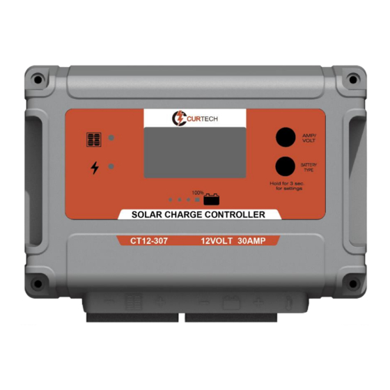
- Page 2 INTRODUCTION • This solar charger controller is designed with PWM (Pulse Width Modulated) technology. • Common negative grounding design and 100% solid state (no fuses or fans). • Suitable for 12V solar systems. • Suitable for most rechargeable batteries: o Crystal battery, Lead acid Flooded (WET), AGM, GEL, and Calcium battery o Lithium ion battery type, targeted for the following 3-SERIES Li-ion battery (see battery type setting on page 8)
- Page 3 WARNING: Risk of explosive gases, working in vicinity of a Lead-acid battery is dangerous. Explosive gases develop during normal battery operation. It is important that each time before using or connecting your solar controller, you read this manual and follow the instructions exactly. •...
- Page 4 FEATURES • PWM technology, switching control by MOSFET • Common negative grounding connection • High efficiency and low power consumption • Battery type setting and battery condition indication • Smart charging control • Charging time management • LED indication for the battery condition and charging status •...
-
Page 5: Installation
INSTALLATION The Solar Controller is mounted as shown below The quickest and easiest way to mount the unit is to use the two plastic spacers and self-tapping screws supplied and mount the unit to a flat surface. Wiring Connections To protect the Battery and the Solar Panel, we strongly recommend that you place an inline fuse on the positive wire on both the “Solar”... - Page 6 Option 1: Connect input and output cables by Anderson connectors (#2 and #3 in the drawing) Take off the rubber mask, directly insert the Anderson connector into the terminal box of the housing case, the metal terminals of Anderson connector will tightly fasten to the metal terminals of the solar controller, when using the Anderson connector, the rubber mask can be fixed at the location #4 in the drawing.
-
Page 7: Wiring Diagram
WIRING DIAGRAM Refer to the below drawing, please cover the solar panel before connecting cables. 20Amp Fuse (for 10Amp Controller) 20Amp Fuse (for 10Amp Controller) 30Amp Fuse (for 20Amp Controller) 30Amp Fuse (for 20Amp Controller) 40Amp Fuse (for 30Amp Controller) 40Amp Fuse (for 30Amp Controller) Correct Wire Size: Please refer to the wire size chart below to determine the minimum size wire needed... - Page 8 OPERATION - LCD DISPLAY Please check your battery manufacturer’s specifications to select correct battery type. The unit provides 8 battery types for selections: Crystal, Lithium-ion, LiFePO4, LTO, Gel, AGM, WET (conventional lead acid), and Calcium battery. Press BATTERY TYPE button and hold for 3 seconds to go into your battery type selection mode, the battery type you select will be shown on the LCD meter, the default setting is AGM Battery;...
- Page 9 When the controller powers on, the unit will run self-qualify mode and automatically show below items on LCD before going into charging process. Self-test starts, digital meter segments test Software version test Rated voltage and current test External battery temperature sensor test (if connected) ºC Indicates the solar panel is connected After going into charging process, the LCD displays the charging status as below:...
- Page 10 CHARGING STAGE The unit has a 6-stage charging algorithm. Diagnose* - Soft Charge - Bulk Charge - Absorption charge - Equalizing Charge* - Float Mode Diagnose* - Only for Lithium battery type, subjected to the Lithium battery initial voltage then determine going to Soft start or Bulk charge; if the Lithium battery is protected by BMS, the controller will automatically send the signal periodically to the battery terminal to activate the BMS against protection.
-
Page 11: Led Indication
LED INDICATION LED Indications Display Backlight LED Colour BLUE BLUE BLUE BLUE GREEN WHITE Soft-start charging FLASH FLASH OFF Bulk charge (charged capacity < 25%) Bulk charge (charged capacity < 50%) OFF FLASH OFF Bulk charge (charged capacity < 75%) OFF FLASH OFF Normal Display... -
Page 12: Specifications
SPECIFICATIONS Electrical Parameters Rated solar panel Amps for CT12-107 / CT12-207 / CT12-307 10/20/30Amp Normal input Solar cell array voltage 15-22VDC Max. solar cell array voltage (output has no load) 25VDC The controller lowest operating voltage at solar or battery side...
Need help?
Do you have a question about the CT12-107 and is the answer not in the manual?
Questions and answers