Table of Contents
Advertisement
Quick Links
RC100C-2 SPECTRUM EFFICIENT GROUND RECEIVER
USER'S GUIDE
Systems Engineering & Management Company
1430 Vantage Court
Vista, California 92081
PROPRIETARY INFORMATION
THE INFORMATION CONTAINED IN THIS DOCUMENT CONSTITUTES PROPRIETARY INFORMATION AND INTELLECTUAL PROPERTY
OF SYSTEMS ENGINEERING & MANAGEMENT COMPANY (SEMCO). ACCORDINGLY, THE USER(S) OF THIS INFORMATION AGREE(S)
TO PROTECT THIS INFORMATION TO THE EXTENT THAT THEY WILL PREVENT OTHERS FROM COPYING AND/OR REPRODUCING
THIS INFORMATION, EITHER IN WHOLE OR IN PART, OR MANUFACTURE, PRODUCE, SELL OR LEASE ANY PRODUCT COPIED FROM
OR ESSENTIALLY REPRODUCED FROM THE INFORMATION CONTAINED IN THIS DOCUMENT WITHOUT THE EXPRESSED WRITTEN
APPROVAL OF SYSTEMS ENGINEERING & MANAGEMENT COMPANY.
DISTRIBUTION STATEMENT
DISTRIBUTION OF THIS DOCUMENT IS AUTHORIZED TO U.S. GOVERNMENT AGENCIES, THEIR CONTRACTORS, AND
INTERNATIONAL USERS WHO HAVE PURCHASED SEMCO'S RC100C-2 SPECTRUM EFFICIENT GROUND RECEIVERS UNDER U.S.
EXPORT RULES AND REGULATIONS. THIS PUBLICATION IS PROVIDED AND REQUIRED SOLELY FOR THE USE AND OPERATION OF
THE RC100C-2 TELEMETRY RECEIVER. OTHER REQUESTS FOR THIS DOCUMENT SHALL BE REFERRED DIRECTLY TO SYSTEMS
ENGINEERING AND MANGEMENT COMPANY
A2537-002/01 February 2020
SEMCO Proprietary Information
Advertisement
Table of Contents

Summary of Contents for Semco RC100C-2
- Page 1 INTERNATIONAL USERS WHO HAVE PURCHASED SEMCO’S RC100C-2 SPECTRUM EFFICIENT GROUND RECEIVERS UNDER U.S. EXPORT RULES AND REGULATIONS. THIS PUBLICATION IS PROVIDED AND REQUIRED SOLELY FOR THE USE AND OPERATION OF THE RC100C-2 TELEMETRY RECEIVER. OTHER REQUESTS FOR THIS DOCUMENT SHALL BE REFERRED DIRECTLY TO SYSTEMS ENGINEERING AND MANGEMENT COMPANY...
- Page 2 When lifting the chassis, always lift from the bottom of the main chassis frame. Electrical – The RC100C-2 SEGR is designed to operate on 115/230 VAC 50/60 Hz and comply with all U.S. and International safety codes and regulations required for safe operation and use of commercial equipment.
- Page 3 LIST OF EFFECTIVE PAGES Page Change Date Page Change Date Initial 04/01/2019 Updates 02/01/2020 A2537-002/01 February 2020 SEMCO Proprietary Information...
-
Page 4: Title Page
IF Demodulator Hardware 3.1.4 Optional Multi-Channel Bit Synchronizer, Frame Synchronizer, BERT and PN Generator 3.1.5 TM over I/P Option 3.1.6 Additional RC100C-2 Hardware SECTION 4 TELEMETRY RF RECEIVER OPERATION RF Frequency Settings 4.1.1 RF Frequency Settings Using Front Panel Controls 4.1.1.1 Front Panel C/CIF-Band Frequency Settings 4.1.2... -
Page 5: Table Of Contents
Additional Advanced Demodulator Settings 6-15 6.8.1 Fast Acquire 6-17 6.8.2 Loop Bandwidth Divider 6-18 6.8.3 FM Sweep 6-19 6.8.4 De-Emphasis and Low Pass Analog Filters 6-20 6.8.5 Modulation Indexing 6-21 6.8.6 Data Quality Metric/Encapsulation (DQM/DQE) 6-23 A2537-002/01 February 2020 SEMCO Proprietary Information... - Page 6 PAGE RC100C-2 Spectrum Efficient Ground Receiver RC100C-2 Initial Power and Remote (Network) Connections (LAN and TM over IP) RC100C-2 SEGR Front Panel LCD Displays and Keypad Remote (Network) GUI Displays Front Panel Keypad Controls Front Panel Display Screen Settings CH1 RF Tuner Settings...
-
Page 7: Tm Over I/P
Load Presets Feature 2-20 2-32 Receiver Help Feature 2-20 RC100C-2 Rear Panel Telemetry I/O RF Frequency Selection (Both CHs) Using Front Panel Displays and Keypad RF Frequency Selection (single CH) Using Front Panel Displays and Keypad RF Frequency Selection from the Tuner Menu... -
Page 8: Title Page
AUTO and Manual Bandwidth and Sweep on Remote GUI 6-15 6-23 Front Panel Fast Acquire Feature 6-17 6-24 Fast Acquire on Remote GUI 6-18 6-25 Front Panel Loop BW Divider Settings 6-18 6-26 Loop BW Divider on Remote GUI 6-19 A2537-002/01 February 2020 SEMCO Proprietary Information... - Page 9 8-15 TM over IP Transmission on Remote GUI 8-11 TABLES TABLE TITLE PAGE RC100C-2 System I/O Demodulator Modes and Features LR, DQM and Correlating BEP Values 6-23 Chapter 10 Data Formats Supported by RC100C-2 A2537-002/01 February 2020 SEMCO Proprietary Information...
- Page 10 Section 2, Getting Started briefly describes and lists the standard and optional hardware features of the SEMCO RC100C-2 SEGR and describes how to install and apply power. Section 2 also walks the user through the features and use of the front panel LCD displays and keypad, as well as installation and use of the System Level Telemetry Software (SLTS) program for RC100C-2 remote (network) operation via Ethernet.
-
Page 11: Rc100C-2 Spectrum Efficient Ground Receiver
IA compliance issues. In addition to the standard and optional features listed below, the RC100C-2 design incorporates a unique feature that makes the system invulnerable to malicious access or control of its ARM processors. A Serial to Ethernet converter with SSH Secure Protocol is used to convert Ethernet TCP/IP packets to RS232 serial data signals and vice versa for bidirectional communication. -
Page 12: Adaptive Equalization (Ae)
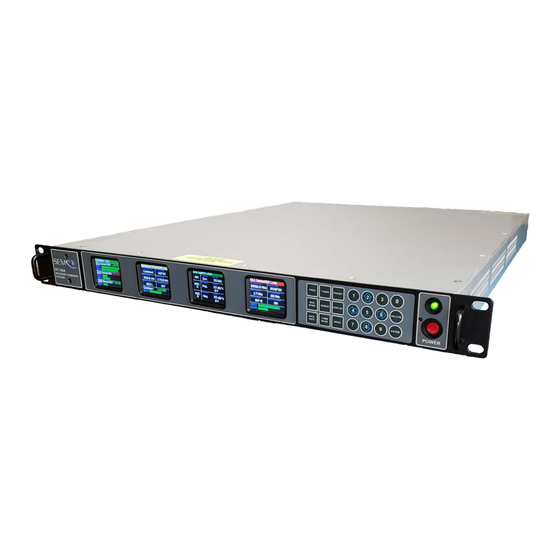
Figure 2-2 illustrates the RC100C-2 front panel displays and keypad controls, as well as rear panel I/O with respect to AC power, local display/keyboard/mouse interface (USB and HDMI) and remote software communications (LAN and TM over IP) via Ethernet. -
Page 13: Rc100C-2 Segr Front Panel Lcd Displays And Keypad
Receiver Software SEMCO-developed software is used for front panel LCD/keypad displays and control (Figure 2-3). All system functions and set-up controls are by remote keyboard entry or via the front panel LCD displays and keypad. System status is via display indicators (numerical readouts and bar graphs) on both the remote GUI display and front panel LCD displays. -
Page 14: Front Panel Keypad Controls
The SLTS interface with the RC100C-2 embedded Linux ARM processor is designed for local operation via RC100C-2 HDMI display/USB interface and/or remotely controlled via Ethernet. SEMCO receivers contain a Low-Level Interface Software (LLIS), which provides a server interface to the receiver hardware in both SEMCO Windows &... - Page 15 15 available selections. For numerical values, enter the number using the keypad. In all cases pressing ENTER will program the selected value to the receiver. Pressing the EXIT (DELETE) button will also exit the current menu. A2537-002/01 February 2020 SEMCO Proprietary Information...
-
Page 16: Front Panel Display Screen Settings
B. Step 2 - Using the DOWN (8) arrow, scroll to Tuner Settings and press ENTER. Then use the DOWN (8) arrow to select Ch1 (highlighted in blue) as shown in Figure 2-6. Figure 2-6 Front Panel Display Screen Settings A2537-002/01 February 2020 SEMCO Proprietary Information... -
Page 17: Ch1 Rf Tuner Settings
(8) arrow, scroll to General Status and press ENTER. The far-right display will now show the general status of the Combiner, CH1 and CH2 as shown in Figure 2-9. Figure 2-9 General Status Display A2537-002/01 February 2020 SEMCO Proprietary Information... -
Page 18: Front Panel Display Settings Example
Steps 1 thru 9 above should be followed to select and position the desired settings on each of the 4 front panel displays. Figure 2-11 Front Panel Display Screen Settings A2537-002/01 February 2020 SEMCO Proprietary Information... -
Page 19: Front Panel Display Settings With Multiple Choice Selection
Figure 2-13 Client and RC100C-2 Network Connections Step 1 - Install the SLTS and Lantronix software application on the Client. The SEMCO SLTS and Lantronix Device Installer icons appear on the Client Desktop as shown in Figure 2-14. Figure 2-14... -
Page 20: Slts Receiver Status Window
Step 2 - Open the SLTS software. If the IP addresses of the connected RC100C-2 receivers are already recognized by the SLTS program, then the Receiver Status Window shown in Figure 2-15 will appear for each connected RC100C-2, and the connected RC100C-2 IP addresses will be listed under IP address. -
Page 21: Entering Receiver Ip Address And Name
Step 3 - Open the SEMCO SLTS remote software and add the new receiver IP Address and Name per Step 4 and Figure 2-17 above. The Control IP Port, Eye Pattern IP Port, and Spec IP Port must also be as shown in Figure 2-17 above. -
Page 22: System Naming Feature
1, Channel 2 and Combiner 1. In the Figure 2-19 example, the System Name (SEMCO DEMO) ties back to the System ID (0DEMO-1907) and its IP Address. Channel 1, Channel 2 and Combiner 1 has been named LHCP, RHCP and LHCP- RHCP, respectively. - Page 23 Users of SEMCO Telemetry receivers that have preceded the RC100C-2 are accustomed to using the GUI design and interface of the Remote Control and Monitor Software (RCMS), both locally and remotely. In so doing, these users will find similarities in SLTS in terms of simplicity and intuitive layout of all displays, menus and controls.
-
Page 24: Slaving Feature On Remote Gui
(8) arrow to select None, Diversity or Frequency and presses ENTER again. Once the desired selection is made, DELETE (EXIT) is pressed to return the display to its original setting. Figure 2-20 Slaving Feature on Remote GUI Figure 2-21 Slaving Feature on Front Panel A2537-002/01 February 2020 2-14 SEMCO Proprietary Information... -
Page 25: System Card Set Selection On Remote Gui
The user clicks on AGC Data Logger and To File, which opens up the AGC Data Logger window. The user then clicks on Select File, chooses the file name and destination and clicks on Save. The file then populates the window under Selected File as shown. A2537-002/01 February 2020 2-15 SEMCO Proprietary Information... -
Page 26: Agc Data/System Parameters Logging
Combiner. These voltages go to zero when the Combiner CH1 Zero and CH2 Zero feature is enabled, and viewing this display confirms this zero function. Figure 2-25 Combiner Zero Feature A2537-002/01 February 2020 2-16 SEMCO Proprietary Information... -
Page 27: Combiner Zero Feature On Front Panel/Keypad
A Spectral Sweep display option is also available with the RC100C-2. The enabling of this feature on the remote GUI as well as the front panel will be addressed in the next revision of this manual. -
Page 28: Eye Pattern And Constellation Feature
DELETE (EXIT) is pressed to return the display to its original setting. Eye Pattern-Q is shown in the Figure 2-29 example. The user repeats these steps for selecting either Eye Pattern-I or Constellation displays. Figure 2-29 Eye Pattern and Constellation Selection Using Front Panel A2537-002/01 February 2020 2-18 SEMCO Proprietary Information... -
Page 29: Save Presets Feature
OK to access the SEMCO Presets directory as shown. Once in the SEMCO Presets directory, the user can now name and save the selected receiver settings as a preset. The naming convention is Preset 1 - (Name), Preset 2 – (Name)…and so forth. -
Page 30: Load Presets Feature
Figure 2-31 shows the Load Presets function on the remote GUI. The user clicks on Presets and then Load to access the SEMCO Preset directory. The user then selects the desired Preset listed in the directory and clicks on Open, which accesses the Load Preset window where the user can select the receivers listed under Select Receivers to be loaded with the selected preset and then press OK as shown. -
Page 31: Rc100C-2 Rear Panel Telemetry I/O
SECTION 3 – HARDWARE I/O Hardware Telemetry I/O Figure 3-1 depicts the RC100C-2 Rear Panel Telemetry I/O outlined in red. The Reference Designators, connectors and a brief description is provided in Table 3-1. Figure 3-1 RC100C-2 Rear Panel Telemetry I/O... - Page 32 3.1.1 Single Card Receiver (SCR) Hardware The RC100C-2 employs 2 Single Card Receiver (SCR) Circuit Card Assemblies (CCAs) that provide for independent RF channel tuning across 200-1150 MHz, 1415-1585 MHz, 1710-1850 MHz, 2185-2485 MHz and 4400-5250 MHz, as well as providing for an independent AM detector, AGC and AFC circuitry and a filtered, linear 70 MHz IF output that is then distributed as required throughout the receiver.
- Page 33 Mbps. Operation can be over a UDP or TCP connection. 3.1.6 Additional RC100C-2 Hardware Additional RC100C-2 hardware includes a Linux ARM Processor; one multi-port ESOM Ethernet-to- Serial/USB adapter; one 10 MHz Reference Oscillator and a Communications and Measurement assembly. A2537-002/01 February 2020...
-
Page 34: Rf Frequency Selection (Both Chs) Using Front Panel Displays And Keypad
This section provides a description and instructions for set-up, operation and status monitoring of the RF Receiver portion of the RC100C-2 SEGR, including but not limited to RF Tuning and down-conversion, 70 MHz linear IF signal distribution, Signal Strength monitoring, IF Filtering, Automatic Frequency Control (AFC), Amplitude Modulation (AM) and Automatic Gain Control (AGC) features. -
Page 35: Rf Frequency Selection From The Tuner Menu
(8) arrow to select ON, and then pushes ENTER or SELECT (5) to turn <Ch2> CIF En. ON. The user then presses DELETE (EXIT) to return the display to its original setting. Figure 4-4 RF CIF Frequency Selection from The Tuner Menu A2537-002/01 February 2020 SEMCO Proprietary Information... -
Page 36: Frequency Up/Down Increment Selection On Remote Gui
The user can change the frequency increments to 1.0 or 10.0 MHz by selecting Edit, Set Defaults and clicking on the desired Frequency Up/Down Increment as shown in Figure 4-6. Figure 4-6 Frequency Up/Down Increment Selection on Remote GUI A2537-002/01 February 2020 SEMCO Proprietary Information... -
Page 37: Entering A Cif-Band Frequency On Remote Gui
(8) arrows to highlight AGC Zero in blue as shown, pushes ENTER or Select to highlight OFF/ON in bright magenta, pushes either the (2) or DOWN (8) arrows to select ON, and then pushes ENTER or SELECT (5) to turn <Ch1> AGC Zero ON. A2537-002/01 February 2020 SEMCO Proprietary Information... -
Page 38: Agc Zero And Relative Rssi Status Settings
(5) to highlight the OFF/ON window in bright magenta. The operator then uses the (2) or DOWN (8) arrows to select ON, and then pushes ENTER or SELECT to enable the <Ch1> Antenna Correction Factor feature. A2537-002/01 February 2020 SEMCO Proprietary Information... -
Page 39: Antenna Signal Strength And Correction Factor Settings
------------------------------------10 dBm Antenna Correction Factor (CF) Value Entered---------------------- Ch1 now indicates an Antenna Signal Strength of -60 dBm with an Absolute RSSI of -70 dBm at Receiver Ch1 RF input Figure 4-10 Antenna Signal Strength and Correction Factor Settings A2537-002/01 February 2020 SEMCO Proprietary Information... -
Page 40: Absolute And Relative Signal Strength Display On Remote Gui
(CF) that represents the signal loss or gain between the antenna and the receiver. The user clicks the small box under Antenna CF and (Antenna) Signal Strength is displayed. A2537-002/01 February 2020 SEMCO Proprietary Information... -
Page 41: Antenna Signal Strength Feature On Remote Gui
The operator uses the (2) and DOWN (8) arrows to select ON, and then pushes ENTER or SELECT (5) to set the <Ch1> Auto IFBW feature. The operator repeats these steps for enabling <Ch2> Auto IFBW. A2537-002/01 February 2020 SEMCO Proprietary Information... -
Page 42: Front Panel If Saw Filter Bandwidth Selection
The operator uses the (2) and DOWN (8) arrows to select the desired IF FIR BW value or Auto and then pushes ENTER or SELECT (5). Figure 4-15 IF FIR Filter Bandwidth Selection A2537-002/01 February 2020 SEMCO Proprietary Information... -
Page 43: If Saw Filter Bandwidth Selection On Remote Gui
IF FIR filter value equal to or greater than the recommended IRIG value for the data rate and demod mode selected. Figure 4-17 IF FIR Filter Bandwidth Selection on Remote GUI A2537-002/01 February 2020 4-10 SEMCO Proprietary Information... -
Page 44: Amplitude Modulation (Am) Settings
Amplitude Modulation (AM) Settings The RC100C-2 AM signal is derived by an analog detector, thus not susceptible to signal latency and the requirement to provide for adjustable delay that is inherent in digital AM demodulation. AM settings include polarity (Normal and Inverted), output impedance (High or Low) and low pass filtering (LPF) between 30 Hz and 30 kHz. -
Page 45: Remote Gui Am Settings
AM polarity to either normal (NORM) or inverted (INV). Clicking on the Impedance box changes the AM output impedance to either High or Low. Figure 4-19 AM LPF Frequency, Polarity and Impedance Selection Using Remote GUI A2537-002/01 February 2020 4-12 SEMCO Proprietary Information... -
Page 46: Agc Settings
SELECT (5). For the Combiner channel, the operator pushes the COMB MODE button and repeats the process. -------------------------------------------------------AGC Slope Selection---------------------------------------------- -----------------------------------------------------AGC Polarity Selection--------------------------------------------- Figure 4-20 AGC Slope and Polarity Selection Using Front Panel A2537-002/01 February 2020 4-13 SEMCO Proprietary Information... -
Page 47: Front Panel Agc Impedance And Time Constant Selection
DOWN (8) arrows to select the desired TC and pushes ENTER or SELECT (5). ----------------------------------------AGC Output Impedance Selection------------------------------------------- ---------------------------------------------AGC Time Constant Selection------------------------------------------ Figure 4-21 AGC Impedance and Time Constant Selection Using Front Panel A2537-002/01 February 2020 4-14 SEMCO Proprietary Information... -
Page 48: Front Panel Agc Zero And Agc Freeze Selection
This feature is only available on the Remote (network) GUI and is further described in paragraph 4.5.8. Figure 4-23 shows how to enable AGC Freeze using the front panel displays and keypad. A2537-002/01 February 2020 4-15 SEMCO Proprietary Information... -
Page 49: Remote Gui Agc Slope And Polarity
AGC voltage output level displays include a Maximum (Max) and Average (Avg) readout by placing the cursor over the AGC Voltage bar graph as shown. Figure 4-24 AGC Slope and Polarity on Remote GUI A2537-002/01 February 2020 4-16 SEMCO Proprietary Information... -
Page 50: Remote Gui Agc Output Impedance
Strength indicator changes to (Relative) Signal Strength when AGC Zero is enabled and the readout is “0 dB” relative to the signal level present when AGC Zero is activated. Figure 4-26 AGC Zero Feature on Remote GUI A2537-002/01 February 2020 4-17 SEMCO Proprietary Information... -
Page 51: Remote Gui Agc Time Constant Selection
Zero enables a pop-up notice with respect to the Attenuator Disable feature that, as previously described is used for more accurate antenna G/T measurements. Right clicking on the AGC Zero button accesses this feature as shown. A2537-002/01 February 2020 4-18 SEMCO Proprietary Information... -
Page 52: 70 Mhz Rf Input And Playback Feature
The rear panel access for this feature is CH1 IF In and CH2 IF In BNC connectors. Figure 4-30 illustrates the front panel set-up for receiving a 70 MHz IF pre-d signal. A2537-002/01 February 2020 4-19 SEMCO Proprietary Information... -
Page 53: 70 Mhz Rf (If) Pre-D And Playback Using Front Panel
Playback button to enable a green indication as shown. The RSSI display is disabled when the Playback feature is enabled. Figure 4-31 70 MHz RF (IF) Pre-d and Playback on Remote GUI A2537-002/01 February 2020 4-20 SEMCO Proprietary Information... -
Page 54: Diversity Combiner Operation
SECTION 5 - DIVERSITY COMBINER OPERATION The RC100C-2 Diversity Combiner is an Optimal Ratio Pre-d Combiner that is designed to process both CH1 and CH2 70 MHz IF signals, as well as CH1 and CH2 AGC and AM outputs, and provide up to 3.0 dB of C/N improvement at equal CH1/CH2 signal level inputs. -
Page 55: Front Panel Combiner Output Mode Selection
Combiner Channel’s Demodulator, and the Combiner Channel rear panel Video Outputs are the baseband video outputs of the selected channel. Figure 5-2 Diversity Combiner Output Mode on Remote GUI A2537-002/01 February 2020 SEMCO Proprietary Information... -
Page 56: Front Panel Combiner Status Indicators
Best Source Selector. Typically, this indicates no signal input, a signal present at only one channel, or either Channel 1 or Channel 2 has been selected as the Combiner output mode. Figure 5-4 Diversity Combiner Status Display on Remote GUI A2537-002/01 February 2020 SEMCO Proprietary Information... -
Page 57: Combiner "Best Source Select" (Bss)
The Combiner “Best Source Select” feature using the remote GUI is shown in Figure 5-6. Clicking on the BSS button toggles the indication OFF and ON. Figure 5-6 Diversity Combiner Best Source Selection on Remote GUI A2537-002/01 February 2020 SEMCO Proprietary Information... -
Page 58: Combiner Zero Feature
Figure 5-8 shows the Combiner Zero Feature on the remote GUI. The user clicks on both the Combiner Zero Rcv1 and Combiner Zero Rcv2 windows to activate this feature, which turns GREEN when ON. Figure 5-8 Combiner Zero Feature on Remote GUI A2537-002/01 February 2020 SEMCO Proprietary Information... -
Page 59: Combiner Agc Slope And Polarity
AGC Slope and AGC Polarity selection on the remote GUI is shown in Figure 5-10. Placing the cursor over the AGC Voltage bar graph provides Maximum and Average AGC readouts during as shown. Figure 5-10 Combiner AGC Slope and Polarity Selection on Remote GUI A2537-002/01 February 2020 SEMCO Proprietary Information... -
Page 60: Agc Output Impedance Selection
ON and then pushes ENTER or SELECT (5). Figure 5-12 Front Panel Combiner AGC Zero Selection Figure 5-13 shows Combiner AGC Zero on the remote GUI. Clicking on the AGC Zero window turns this feature ON. A2537-002/01 February 2020 SEMCO Proprietary Information... -
Page 61: Combiner Agc Zero Feature On Remote Gui
Figure 5-13 Combiner AGC Zero Feature on Remote GUI A2537-002/01 February 2020 SEMCO Proprietary Information... -
Page 62: Demodulator And Embedded Bit Synchronizer Operation
SECTION 6 - DEMODULATOR AND EMBEDDED BIT SYNCHRONIZER OPERATION Overview The three RC100C-2 Demodulators and embedded Bit Synchronizers are FPGA-based designs that function independently. These demodulators and embedded bit synchronizers are designed to support all modulation formats and emerging technologies used at both U.S. and international flight test ranges. -
Page 63: Demod Mode Selection Using Front Panel Demod Controls
(4) and RIGHT (6) arrows to change the Modulation Input display bar as shown in Figure 6-3 and then push ENTER or SELECT (5). Figure 6-3 Demod Mode Selection in Individual or Multiple Channels A2537-002/01 February 2020 SEMCO Proprietary Information... -
Page 64: Demodulator Data Rate Entry
Push DATA RATE button 2 times - Ch1 Push DATA RATE button 3 times - Ch2 Push DATA RATE button 4 times - Combiner Pushing the DATA RATE button 5 times exits the menu. A2537-002/01 February 2020 SEMCO Proprietary Information... -
Page 65: Individual Demodulator Data Rate Selection
AQPSK or AUQPSK demodulator format is selected. This allows the user to type in desired different (“Asynchronous”) data rates for the I and Q data streams. The steps previously described and illustrated in Figure 6-8 is used to enter both Data Rate A and Data Rate B values. A2537-002/01 February 2020 SEMCO Proprietary Information... -
Page 66: I And Q Data Rate Entry On Front Panel
AQPSK or AUQPSK demodulator format is selected. This allows the user to type in desired different (“Asynchronous”) data rates for the I and Q data streams. Figure 6-10 I and Q Data Rate Entry on Remote GUI A2537-002/01 February 2020 SEMCO Proprietary Information... -
Page 67: Qpsk Data Rate Entry
BASEBAND VIDEO BW value and pushes ENTER or Select (5). As previously mentioned, the Baseband Video BW value only needs to be entered once for all 3 channels if Diversity Slaving is enabled. Figure 6-11 Front Panel Video FIR Filter BW Selection A2537-002/01 February 2020 SEMCO Proprietary Information... -
Page 68: Front Panel Analog Video Gain Selection
0 to >4 Vp-p into 75 ohms. The slide bar is expressed as a 0 to 15 dB readout. Two slide bars are displayed for QPSK, A/U/QPSK and SOQPSK analog I and Q baseband video outputs. A2537-002/01 February 2020 SEMCO Proprietary Information... -
Page 69: Embedded Bit Synchronizer Features
Menu header display bar, pushes ENTER or SELECT (5) to highlight the selection window in bright magenta, uses the (2) and DOWN (8) arrows to select ON and then pushes ENTER or SELECT (5). A2537-002/01 February 2020 SEMCO Proprietary Information... -
Page 70: Enabling The Bit Sync De-Randomizer Using The Front Panel
(8) arrows to select INPUT CODE and then pushes ENTER or SELECT (5). As previously mentioned, all 3 channel settings are set-up simultaneously if Diversity Slaving is enabled. Figure 6-15 Selecting Bit Sync De-Randomizer Input Codes Using the Front Panel A2537-002/01 February 2020 SEMCO Proprietary Information... -
Page 71: Remote Gui De-Randomizer And Input Code Selection
(5) to highlight the selection window in bright magenta, uses (2) and DOWN (8) arrows to select a Clock Phase and then pushes ENTER or SELECT (5). Figure 6-17 Embedded Bit Sync Clock Phase Settings Using Front Panel A2537-002/01 February 2020 6-10 SEMCO Proprietary Information... -
Page 72: I/Q Interleaving
(5) to highlight the selection window in bright magenta, uses the (2) and DOWN (8) arrows to select ON and then pushes ENTER or SELECT (5). Figure 6-19 Front Panel I/Q Interleaving Selection A2537-002/01 February 2020 6-11 SEMCO Proprietary Information... -
Page 73: Auto Demodulator Settings
Here again, a wider demodulator loop bandwidth will require a higher C/N threshold to lock. The Auto Bandwidths feature calculates and sets an optimum value that provides for a lock threshold that applies to most data rates and demod formats. A2537-002/01 February 2020 6-12 SEMCO Proprietary Information... -
Page 74: Auto Loop Bandwidths, Sweep Range And Sweep Rate Settings
(5) to highlight the AUTO SWEEP RANGE selection window in bright magenta. The operator then uses the (2) and DOWN (8) arrows to select ON and pushes ENTER or SELECT (5). The operator repeats these steps for <Comb>. A2537-002/01 February 2020 6-13 SEMCO Proprietary Information... -
Page 75: Front Panel Auto Bandwidth And Sweep Settings
(5) to highlight the respective selection window in bright magenta. The operator then uses the numerical keypad to enter the desired BANDWIDTH, SWEEP RANGE and/or SWEEP RATE value and pushes ENTER or Select (5). A2537-002/01 February 2020 6-14 SEMCO Proprietary Information... -
Page 76: Additional Advanced Demodulator Settings
Selecting this mode may slightly degrade the lock threshold of the selected demodulator mode but will provide for faster acquisition time and improve Trellis FM lock time to less than 250 average bits and SOQPSK-TG lock time to less than 350 average bits. A2537-002/01 February 2020 6-15 SEMCO Proprietary Information... - Page 77 These signals are typically delayed in time and have differing amplitudes. A2537-002/01 February 2020 6-16 SEMCO Proprietary Information...
-
Page 78: Fast Acquire
Front Panel Fast Acquire Feature Figure 6-24 shows how to enable Fast Acquire on the remote GUI. The user clicks on Advanced Settings and then the Fast Acquire window, which toggles ON/OFF as shown. A2537-002/01 February 2020 6-17 SEMCO Proprietary Information... -
Page 79: Loop Bandwidth Divider
(8) arrows to select one of the 4 Loop Bandwidth Divider values and pushes ENTER or SELECT (5). The operator repeats these steps for <Comb>. Figure 6-25 Front Panel Loop BW Divider Settings A2537-002/01 February 2020 6-18 SEMCO Proprietary Information... -
Page 80: Fm Sweep
The operator then uses the (2) and DOWN (8) arrows to select ON and pushes ENTER or SELECT (5). The operator repeats these steps for <Comb>. Figure 6-27 Front Panel FM Sweep Settings A2537-002/01 February 2020 6-19 SEMCO Proprietary Information... -
Page 81: Emphasis And Low Pass Analog Filters
(8) arrows to select Bypass, De-Emph, 6 MHz LPF or 27 MHz LPF and pushes ENTER or SELECT (5). The operator repeats these steps for <Comb>. Figure 6-29 Front Panel Video De-Emphasis and Low Pass Filter Setting A2537-002/01 February 2020 6-20 SEMCO Proprietary Information... -
Page 82: Modulation Indexing
(6) arrows, the operator selects <Ch2> and pushes ENTER or SELECT (5) to highlight the selection window in bright magenta. The selection window indicates Auto, and the operator then pushes ENTER or SELECT (5). The operator repeats these steps for <Comb>. A2537-002/01 February 2020 6-21 SEMCO Proprietary Information... -
Page 83: Front Panel Auto Modulation Index Settings
0.00, the operator uses the numerical keypad to enter a Mod Index value between 0.3 and 0.4 and then pushes ENTER or Select (5). The operator repeats these steps for <Comb>. Figure 6-32 Front Panel Manual Modulation Index Settings A2537-002/01 February 2020 6-22 SEMCO Proprietary Information... -
Page 84: Data Quality Metric/Encapsulation (Dqm/Dqe)
BEP and computing a Likelihood Ratio (LR), which is then used to represent the data quality. Using the calculated LR, the DQM is then calculated as a 16-bit unsigned integer. Table 6-2 shows the relationship of BEP, LR & DQM. Table 6-2 LR, DQM and Correlating BEP Values A2537-002/01 February 2020 6-23 SEMCO Proprietary Information... -
Page 85: Encapsulation Structure
D. DQM - The 16-bit calculated Data Quality Metric as defined above. E. PAYLOAD - 1024 to 16384 Bits of received data. The RC100C-2 SEGR DQM setup, as described in subsequent paragraphs, addresses the following parameters: A. Enable - Setting this control enables the operation of DQM/DQE. Operation is only valid in PCM/FM, SOQPSK and Multi-h CPM demodulation formats. -
Page 86: Dqm Frame Size Using Front Panel Lcds And Keypad
Using the remote GUI, the user clicks on the DQM window, which toggles ON/OFF as shown in Figure 6- 37. The user then clicks on Advanced Settings to access DQM Frame Size, types in the Frame Size value and clicks on Keyboard return. A2537-002/01 February 2020 6-25 SEMCO Proprietary Information... -
Page 87: Dqm Setup On Remote Gui
The operator then uses the (2) and DOWN (8) arrows to select ON and pushes ENTER or SELECT (5). The operator repeats these steps for <Comb>. Figure 6-38 Front Panel AE Selection A2537-002/01 February 2020 6-26 SEMCO Proprietary Information... -
Page 88: Low Density Parity Check (Ldpc) Fec
ENTER or SELECT (5). Using the horizontal LEFT (4) and RIGHT (6) arrows again, the operator selects <Comb> in the Demod Menu header display bar and repeats the process for selecting Combiner LDPC. A2537-002/01 February 2020 6-27 SEMCO Proprietary Information... -
Page 89: Soqpsk-Ldpc Mode Selection Using Front Panel Using
(4) and RIGHT (6) arrows to change the Modulation Input display bar as shown in Figure 6-42 and then push ENTER or SELECT (5). Figure 6-42 SOQPSK-LDPC Selection in Individual or Multiple Channels A2537-002/01 February 2020 6-28 SEMCO Proprietary Information... -
Page 90: Front Panel Soqpsk-Ldpc Settings
The operator then uses the (2) and DOWN (8) arrows to select CCSDS or IRIG and pushes ENTER or SELECT (5). The operator repeats these steps for <Comb>. ---------------------------------------------SOQPSK-LDPC Rate Selection------------------------------------------- Figure 6-43 Front Panel SOQPSK-LDPC Settings A2537-002/01 February 2020 6-29 SEMCO Proprietary Information... -
Page 91: Soqpsk-Ldpc Settings On Remote Gui
2/3 or 1/2 rate from the pull-down menu. The LDPC De-randomizer is selected by clicking on the arrow in the DeRandom window and selecting Off, CCSDS or IRIG from the pull-down menu. SOQPSK-LDPC Selection LDPC Block Size Selection LDPC Rate Selection Figure 6-44 SOQPSK-LDPC Settings on Remote GUI A2537-002/01 February 2020 6-30 SEMCO Proprietary Information... -
Page 92: Space Time Coding (Stc)
SOQPSG-STC signal. Specific instructions for setting up, controlling and displaying applicable information on both the Front Panel LCD/Keypad and remote GUI is scheduled to be incorporated in the next revision to this manual. A2537-002/01 February 2020 6-31 SEMCO Proprietary Information... -
Page 93: Bit Sync/Frame Sync And Bert Option
Sync/Frame Sync/BERT or used in conjunction with each channel’s demodulator output for TTL and RS422 bit sync/frame sync outputs, as well as BER loop testing of each receiver and combiner channel. This option will be included in the next revision to this manual. A2537-002/01 February 2020 SEMCO Proprietary Information... -
Page 94: Pcm Tm Over Ip
Chapter 10 TM over IP The RC100C-2 TM over IP feature also supports IRIG 106-17 Chapter 10 packets, which are further specified in IRIG 106-17 Chapter 11. The receiver can support Time Data, Format 1 (IRIG/GPS/RTC) as defined in RCC Document 106-17, Telemetry Standard, Chapter 11, July 2017, section 11.2.1.1, table 11- 4, which is reproduced in Table 8-1. -
Page 95: Chapter 10 Data Formats Supported By Rc100C-2
Table 8-1 Chapter 10 Data Formats Supported by RC100C-2 Packet Data Type Name Data Type Description Current Data Header Value Type Version 0x00 Computer-Generated Data, Format 0 User - Defined 0x06 0x01 Computer-Generated Data, Format 1 Setup Record 0x08 0x02... -
Page 96: General Chapter 10 Packet Structure
11.2.1. Timing is transmitted as specified in IRIG Chapter 11 section 11.2.3.2 and is treated like another data channel. The general time packet structure is shown in Figure 8-3. Figure 8-3 General Time Packet A2537-002/01 February 2020 SEMCO Proprietary Information... -
Page 97: Time Source
IP Address, Netmask and Gateway Settings on Remote GUI 8.4.1 Time Source Using the remote GUI, each of the receiver’s TM over IP Channel Settings are accessed by clicking on PCM 1, PCM 2 or PCM 3 as shown in Figure 8-6. A2537-002/01 February 2020 SEMCO Proprietary Information... -
Page 98: Tm Over Ip Channel Settings On Remote Gui
IP devices that can only be used as the destination of a Multicast datagram. The user should consult with their IT department to be sure that the network is configured to properly handle Multicast traffic before choosing this selection. A2537-002/01 February 2020 SEMCO Proprietary Information... -
Page 99: Protocol Settings On Remote Gui
Establishing remote IP addresses using the remote GUI are shown in Figure 8-8. The user clicks on the Remote IP window as shown, types in the remote IP address and Enter on the keyboard. Figure 8-8 Remote IP Address Entry on Remote GUI A2537-002/01 February 2020 SEMCO Proprietary Information... -
Page 100: Data Port Entry On Remote Gui
Data Header selection using the remote GUI is shown in Figure 8-10. The user clicks on the arrow icon next to the Data Header window, which accesses a pull-down window as shown. The user then selects TM over IP, Time+TMoIP or CH10. A2537-002/01 February 2020 SEMCO Proprietary Information... -
Page 101: Data Header Selection On Remote Gui
Input Imped. window, which accesses a pull-down window as shown. The user then selects 50 , 75 or High Z. Ω Ω Figure 8-11 Input Termination Selection on Remote GUI A2537-002/01 February 2020 SEMCO Proprietary Information... -
Page 102: Data Buffering Selection On Remote Gui
Entering MTU Size values using the remote GUI is shown in Figure 8-13. The user clicks on the MTU Size window as shown, types in the MTU Size value and Enter on the keyboard. A2537-002/01 February 2020 SEMCO Proprietary Information... -
Page 103: Mtu Size Entry On Remote Gui
Entering an Rx Buffers value using the remote GUI is shown in Figure 8-14. The user clicks on the Rx Buffers (ms) window as shown, types in the Rx Buffer value and Enter on the keyboard. Figure 8-14 Rx Buffer Entry on Remote GUI A2537-002/01 February 2020 8-10 SEMCO Proprietary Information... -
Page 104: Tm Over Ip Transmission On Remote Gui
ON, indicating that Data Transmission has commenced. The Input 1, Input 2 and Input 3 indicators turn RED indicating Channel Transmission (Input 2 shown as example). Figure 8-15 TM over IP Transmission on Remote GUI A2537-002/01 February 2020 8-11 SEMCO Proprietary Information...
Need help?
Do you have a question about the RC100C-2 and is the answer not in the manual?
Questions and answers